Hyundai i-30: Autonomous Emergency Braking (AEB) System / AEB Camera
Repair procedures
|
1. |
Disconnect the negative (-) battery terminal.
|
|
2. |
Remove the MFC unit cover (A).
|
|
3. |
Disconnect the MFC unit connector (A).
|
|
4. |
Separate the fixed points (A) of coupler, remove the MFC (B).
|
• |
When separate the fixed points, be careful not to damage
it.
|
|
|
|
1. |
To install, reverse the removal procedure.
|
|
2. |
If exchange the camera, perform variant coding.
|
|
3. |
Perform the SPTAC Calibration.
|
|
When you need variant coding:
| –
|
Replace MFC with a new one
|
※ EOL Variant Coding and calibration required for new replacement
|
MFC Variant Coding
MFC variant coding makes it possible to operate functions for each vehicle type.
If the variant coding differs from the vehicle specification, the "variant coding
error" DTC is displayed.
|
1. |
Procedure for coding variants
|
(1) |
You should read the specification information for the MFC that
is installed in the vehicle before replacing it with a new MFC.
|
|
(2) |
Select specification information from G-SCAN's additional function.
|
|
(3) |
Enter the value of the specification read in procedure(2) in
the new MFC.
|
|
Service Point Target Auto Calibration (SPTAC)
This procedure provides a way to calibrate the camera by having the service
technician align the car to a well lit simulated straight road target; preferably
wall mounted. The MFC will have a "System Out of Calibration" DTC set if not
operating within specified tolerances.
|
When you need calibration:
| –
|
MFC is removed and mounted
|
| –
|
Replace MFC with a new one
|
※ EOL Variant Coding and calibration required for new replacement
| –
|
Windshield glass changed
|
| –
|
MFC coupler of the windshield glass is deformed
|
|
|
1. |
Guidelines for Selecting a Suitable Target
In order for LKAS Service Calibration-Static routine to complete successfully,
the following conditions are required:
| –
|
The surface of the target (special tool: 09890-3V100) must maintain
a right angle of up to 1 degree in both horizontal and vertical
directions from the camera.
|
| –
|
The tolerance for the parallel axis with the bumper of the target
is ± 10 ° and the tolerance for the vertical axis of the ground
is ± 5 °.
|
| –
|
The target must be made of a rigid material to satisfy the flatness.
|
| –
|
Target has reflective (not faded or poorly painted) markings
that are unlike from lane features.
|
| –
|
Target is 30 cm wide and 100 cm tall.
|
| –
|
Mounting area must NOT have cross hatch patterns or textual
markings near the target.
|
| –
|
Target should be well lit for optimal performance using non-fluctuating
illumination. There shall be no continuous shadows cast on the
target.
|
| –
|
The light should be directed toward the target front and the
target front should be brighter than the target rear and target.
|
|
|
2. |
Service Point Target Auto Calibration(SPTAC) Procedure
|
(1) |
It is recommended to check vehicle toe-in and tire pressure
levels to ensure proper alignment of the camera to the "world"
before proceeding with calibration. The vehicle to run the calibration
routine is to be at nominal production loading capacity.
|
|
(2) |
Windshield must be clean and silk-screen checked so that there
is no blockage of the camera.
|
|
(3) |
Service technician connects the diagnostic connector and starts
the vehicle. The MFC should not be activated by pressing the
switch.
|
| –
|
If you place an object on the top of the crash pad, it may be
reflected and may interfere with the SPTAC.
|
|
(4) |
The service calibration routine may not run correctly if any
system level fault is active.
|
|
(5) |
If working with a replacement ECU: the service technician initiates
the SPTAC Reset configuration.
|
|
(6) |
Service technician either aligns the vehicle to the target or
the target to the vehicle.
|
a. Bottom of the target is 90 ± 1 cm (35.4 ± 0.4in.) from the ground
b. The target (A) is placed along the vehicle’s longitudinal axis (centerline)
within 3 cm (1.2in.) of target center.
c. The position of target (A) in short distance is 0± 5cm (0.2in.) (B)
in front of front bumper. (Maximum error : 5cm)
d. The position of target (A) in long distance is 100±5cm (39.4±2 in.)
(B) in front of front bumper. (Maximum error : 5cm)
e. The horizontal displacement is should be within ± 3 cm (± 1.2 in.)
with the center axis.
(7) After confirming the calibration target location in close distance,
click "OK" on diagnostic device.
(8) Technician ensures target placement location and checks the "OK"
message on the diagnostic tool(diagnostic tool).
|
Test Drive
| –
|
Be sure to perform test drive to check for normal operation
after performing calibration.
|
| –
|
Drive on straight road (of longer than 500 m) with 2 white or
yellow lane marks at speed of over 60km/h (64mph), and check
for the alert as you intentionally steer close to the lane mark.
|
| –
|
LKAS operates properly if the lane mark segment space is less
than 8 m.
|
| –
|
It is carried out on a motorway or highway.
|
| –
|
The LDWS / LKAS operates at a vehicle speed of 60 km / h or
more.
|
|
|
Be careful because it may not operate normally under the following conditions.
| –
|
When the lane is not seen as backlight, bad weather, rainwater,
etc.
|
| –
|
When there is snow on the road.
|
| –
|
When the streetlight or opposite car is reflected on the water
left on the road after rain.
|
| –
|
When there is a boundary structure such as a sidewalk block
on the road edge.
|
| –
|
When there are traces other than lane due to road maintenance.
|
| –
|
When the distance from the front car is extremely short.173
|
|
Repair procedures
Removal
1.
Remove the bumper.
(Refer to Body - "Front Bumper")
2...
Other information:
To set Vehicle-to-Vehicle
Distance
When the Smart Cruise Control
System is ON, you can set and maintain
the distance from the vehicle
ahead of you without pressing the
accelerator or brake pedal.
Each time the button is pressed, the
vehicle to vehicle distance changes
as follows:
For example, if you drive at 56 mph
(90 km/h), the distance maintain as
follows:
Distance 4 - approximately 172 feet
(52...
Component Location
1. Windshield
wiper arm & blade
2. Wiper & washer switch
3. Windshield washer hose & nolzzle
4. Wiper motor & linkage assembly
5. Washer motor
6. Washer reservoir tank
7...
Categories
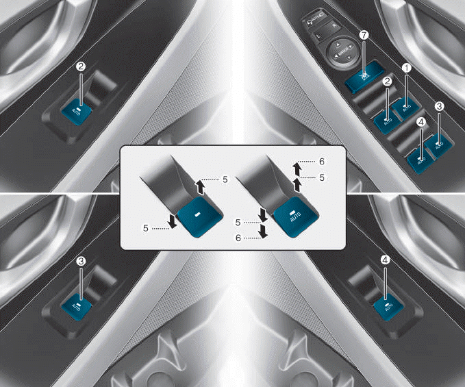
(1) Driver’s door power window
switch
(2) Front passenger’s door power
window switch
(3) Rear door (right) power window
switch
(4) Rear door (left) power window
switch
(5) Window opening and closing
(6) Automatic power window
(7) Power window lock switch
read more


 AEB Radar
