Hyundai i-30: Air Conditioning System / Auto Defogging Sensor

Hyundai i30 (PD) 2018-2024 Service Manual / Heating, Ventilation and Air Conditioning / Air Conditioning System / Auto Defogging Sensor

Description and operation
Description
The auto defogging sensor is installed on the front window glass. The sensor judges and sends signal if moisture occurs to blow out wind for defogging. The air conditioner control module receives signal from the sensor and restrains moisture and eliminate defog by controlling the intake actuator, A/C, auto defogging actuator, blower motor rpm, and mode actuator.
Repair procedures
Diagnosis With GDS
1.
The heating, ventilation and air conditioning can be quickly diagnosed failed parts with vehicle diagnostic system (GDS).
※ The diagnostic system (GDS) provides the following information.
(1) Self diagnosis : Checking the failure code (DTC) and display.
(2) Current data : Checking the system input/output data state.
(3) Actuation test : Checking the system operation condition.
(4) Additional function : Other controlling such as he system option and zero point adjustment.
2.
Select the 'Car model' and the system to be checked in order to check the vehicle with the tester.
3.
Select the 'Current data' menu to search the current state of the input / output data.
The input / output data for the sensors corresponding to the Auto Defogging Sensor can be checked.

Replacement
1.
Disconnect the negative (-) battery terminal.
2.
Remove the auto defogging cover (A).

3.
Disconnect the connector (A) and then remove the auto defogging sensor (B).

4.
To install, reverse the removal procedure.

    Ambient Temperature Sensor

    Description and operation Description The ambient temperature sensor is located at the front of the condenser and detects ambient air temperature...

    Cluster Ionizer

    Components and components location Components Location 1. Cluster lonizer Description and operation Description The cluster ionizer makes disinfection and decomposition of bad smell from the air-conditioner or inflow air...

    Other information:

    Hyundai i30 (PD) 2018-2024 Service Manual: Cooling Fan


    Components and components location Components 1. Cooling fan 2. Fan motor 3. Cooling fan shroud 4. Cooling fan controller (PWM) Repair procedures Removal and installation Cooling Fan 1...

    Hyundai i30 (PD) 2018-2024 Service Manual: Engine Control Module (ECM)


    Schematic diagrams ECM Terminal and Input / Output signal ECM Harness Connector ECM Terminal Function Connector [A] Terminal Description 1 Fuel Pressure Regulator Valve (FPRV) [High] Control 2 Integrated Thermal Management Module (ITM) Motor (+) 3 Integrated Thermal Management Module (ITM) Motor (-) 4 Exhaust Gas Temperature Sensor (EGTS) #2 (T4) Ground [GPF Type] 5 Engine Coolant Temperature Sensor (ECTS) #1 Ground 6 - 7 Engine Coolant Temperature Sensor (ECTS) #2 Ground 8 Differential Pressure Valve (DPV) Ground 9 Rail Pressure Sensor (RPS) Ground 10 Exhaust Gas Temperature Sensor (EGTS) Ground 11 Manifold Absolute Pressure Sensor (MAPS) Ground 12 Electric Waste Gate Control Actuator (EWGA) Ground 13 EGR Pressure Sensor Ground 14 Oil Pressure & Temperature Sensors (OPTS) Ground 15 Electric Exhaust Gas Recirculation (EEGR) Control Valve Ground 16 - 17 A/C Pressure Transducer (APT) Ground 18 Sensor Power (+5V) (Camshaft Position Sensor (CMPS) [Bank 1 / Intake, Exhaust]) 19 Sensor Power (+5V) (Manifold Absolute Pressure Sensor (MAPS)) Sensor Power (+5V) (Electric Exhaust Gas Recirculation (EEGR)) Sensor Power (+5V) (Crankshaft Position Sensor (CKPS)) 20 Sensor Power (+5V) (Oil Pressure & Temperature Sensors (OPTS)) Sensor Power (+5V) (Electric Throttle Control Module (ETC)) Sensor Power (+5V) (Rail Pressure Sensor (RPS)) 21 Throttle Position Sensor (TPS) Ground 22 Electric Exhaust Gas Recirculation (EEGR) Control Valve Motor (+) 23 Electric Exhaust Gas Recirculation (EEGR) Control Valve Motor (-) 24 Knock Sensor (KS ) Shield Ground 25 - 26 Ignition Coil (Cylider #3) Control 27 - 28 - 29 Exhaust Gas Temperature Sensor (EGTS) #1 (T3) Ground [GPF Type] 30 - 31 - 32 - 33 EGR Pressure Sensor Signal 34 - 35 Integrated Thermal Management Module (ITM) Motor Ground 36 - 37 Camshaft Position Sensor (CMPS) [Bank 1 / Intake] Signal 38 - 39 Electric Waste Gate Control Actuator (EWGA) Signal 40 Sensor Power (+5V) (EGR Pressure Sensor) Sensor Power (+5V) (Electric Waste Gate Control Actuator (EWGA)) 41 Sensor Power (+5V) (Accelerator Position Sensor (APS #1)) 42 Sensor Power (+5V) (Brake Booster Vacuum Pressure Sensor (BBVPS)) Sensor Power (+5V) (A/C Pressure Transducer (APT)) 43 Injector (Cylinder #3) [+] Control 44 Injector (Cylinder #2) [+] Control 45 - 46 - 47 CCP-CAN [High] 48 Ignition Coil (Cylinder #1) Control 49 - 50 Neutral Switch [With ISG] 51 - 52 - 53 - 54 Exhaust Gas Temperature Sensor (EGTS) #1 (T3) Signal [GPF Type] 55 - 56 Exhaust Gas Temperature Sensor (EGTS) #2 (T4) Signal [GPF Type] 57 - 58 Differential Pressure Sensor (DPS) Signal 59 Exhaust Gas Temperature Sensor (EGTS) Signal 60 Camshaft Position Sensor (CMPS) [Bank 1 / Exhaust] Ground 61 Mass Air Flow Sensor (MAFS) Signal 62 - 63 Engine Speed Signal Output 64 Injector (Cylinder #1) [+] Control 65 Injector (Cylinder #4) [+] Control 66 Injector (Cylinder #3) [-] Control 67 Injector (Cylinder #4) [-] Control 68 Ignition Coil (Cylider #2) Control 69 CCP-CAN [Low] 70 Camshaft Position Sensor (CMPS) [Bank 1 / Exhaust] Signal 71 Crankshaft Position Sensor (CKPS) Ground 72 Ignition Lock Switch [M/T & Without Smart Key] 73 Oil Pressure Sensor (OPS) Signal 74 Intake Air Temperature Sensor (IATS) Signal 75 Engine Coolant Temperature Sensor (ECTS) #1 Signal 76 Engine Coolant Temperature Sensor (ECTS) #2 Signal 77 Electric Exhaust Gas Recirculation (EEGR) Control Valve Signal 78 Differential Pressure Valve (DPV) Signal 79 Throttle Position Sensor (TPS) #2 Signal 80 Rail Pressure Sensor (RPS) Signal 81 - 82 Integrated Thermal Management Module (ITM) Motor Signal 83 Mass Air Flow Sensor (MAFS) Ground 84 A/C Pressure Transducer (APT) Signal 85 - 86 Injector (Cylinder #2) [-] Control 87 Injector (Cylinder #1) [-] Control 88 Fuel Pressure Regulator Valve (FPRV) [Low] Control 89 Differential Pressure Sensor (DPS) Ground 90 Ignition Coil (Cylinder #4) Control 91 Crankshaft Position Sensor (CKPS) Signal 92 - 93 Heated Oxygen Sensor (HO2S) [Bank 1 / Sensor 2] Ground 94 - 95 Heated Oxygen Sensor (HO2S) [Bank 1 / Sensor 2] Signal 96 - 97 Oil Temperature Sensor (OTS) Signal 98 Throttle Position Sensor (TPS) #1 Signal 99 - 100 - 101 Manifold Absolute Pressure Sensor (MAPS) Signal 102 Camshaft Position Sensor (CMPS) [Bank 1/Intake] Ground 103 - 104 Knock Sensor (KS) Signal 105 Knock Sensor (KS) Ground Connector [B] Terminal Description 1 Chassis Ground 2 Chassis Ground 3 Battery Power (B+) (Battery) 4 Chassis Ground 5 Battery Power (B+) (Main Relay) 6 Battery Power (B+) (Main Relay) 7 - 8 - 9 Sensor Power (+5V) (Integrated Thermal Management Module (ITM) Motor) Sensor Power (+5V) (Mass Air Flow Sensor (MAFS)) 10 Sensor Power (+5V) (Accelerator Position Sensor (APS) #2) 11 Boost Pressure Sensor (BPS) Signal Input 12 Accelerator Position Sensor (APS) #2 Ground 13 Accelerator Position Sensor (APS) #1 Ground 14 Brake Booster Vacuum Pressure Sensor (BBVPS) Ground [With ISG] 15 - 16 Boost Pressure Sensor (BPS) Ground 17 Fuel Level Sender (FLS) Signal 18 Accelerator Position Sensor (APS #2) Signal 19 - 20 - 21 - 22 RCV Control Solenoid Valve Control 23 Cooling Fan Relay [PWM] Control 24 Electric Waste Gate Control Actuator (EWGA) DC Motor (+) Control 25 Electric Waste Gate Control Actuator (EWGA) DC Motor (-) Control 26 Ignition Switch Signal Input 27 Sensor Power (+5V) (Differential Pressure Sensor (DPS)) Sensor Power (+5V) (Differential Pressure Valve (DPV)) Sensor Power (+5V) (Boost Pressure Sensor (BPS)) 28 - 29 - 30 Brake Light Switch Signal Input 31 Brake Test Switch Signal Input 32 Accelerator Position Sensor (APS #1) Signal 33 - 34 ISG OFF Switch Signal Input [With ISG] 35 Start Signal Input 36 - 37 Fuel Pump Relay Control [W/O Smart Key] 38 DC/DC Converter (LDC) Control [With ISG] 39 - 40 Variable Oil Pump Valve Control 41 ETC Motor [+] Control 42 ETC Motor [-] Control 43 - 44 LIN communication signal input 45 C-CAN (Low) 46 - 47 - 48 Clutch Switch [M/T] 49 Wiper Switch Signal Input 50 Blower Motor MAX Input 51 Start Relay Control (Low Side) 52 - 53 - 54 Rear Defrost Switch Signal Input 55 - 56 - 57 - 58 Differential Pressure Valve (DPV) DC Motor (+) Control 59 Differential Pressure Valve (DPV) DC Motor (-) Control 60 Battery Power (B+) (Battery) 61 LIN Communication Signal input 62 C-CAN (High) 63 Brake Booster Vacuum Pressure Sensor (BBVPS) Signal [With ISG] 64 Heated Oxygen Sensor (HO2S) [Bank 1 / Sensor 1] VS+ (NERNST Cell Voltage) 65 Heated Oxygen Sensor (HO2S) [Bank 1 / Sensor 1] Rc (Compensative Resistance) 66 Heated Oxygen Sensor (HO2S) [Bank 1 / Sensor 1] Rc/Rp (Pump Cell Voltage) 67 Heated Oxygen Sensor (HO2S) [Bank 1 / Sensor 1] VS-/IP- (Common Ground for VS, IP) 68 - 69 A/C Compressor Relay Control 70 - 71 Start Relay Control (High side) 72 - 73 - 74 Engine Control Relay Control 75 Heated Oxygen Sensor (HO2S) [Bank 1 / Sensor 1] Heater Control 76 Heated Oxygen Sensor (HO2S) [Bank 1 / Sensor 2] Heater Control 77 Vehicle Speed Signal Input 78 CCP-CAN [High] 79 CCP-CAN [Low] 80 - 81 - 82 - 83 Purge Control Solenoid Valve (PCSV) Control 84 Fuel Pump Relay Control [With Smart Key] 85 ISG OFF Switch (IND...

    Categories

    Door locks

    Operating door locks from outside the vehicle

    Mechanical key

    Hyundai i30. Door locks

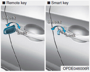
    Turn the key toward the rear of the vehicle to unlock and toward the front of the vehicle to lock.

    If you lock/unlock the driver's door with a key, a driver’s door will lock/unlock automatically.

    read more


    Copyright © 2024 www.hi30.net