Hyundai i30 (PD): Maintenance / Engine coolant
The high-pressure cooling system has a reservoir filled with year-round antifreeze coolant. The reservoir is filled at the factory.
Check the antifreeze protection and coolant concentration level at least once a year, at the beginning of the winter season, and before travelling to a colder climate.
NOTICE
- When the engine overheats from low engine coolant, suddenly adding engine coolant may cause cracks in the engine. To prevent damage, add engine coolant slowly in small quantities.
- Do not drive with no engine coolant. It may cause water pump failure and engine seizure, etc.
Checking the engine coolant level
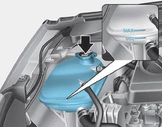
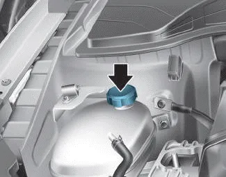
â– Type A
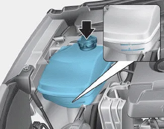
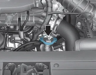
â– Type B
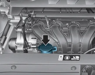
â– Type C
Check the condition and connections of all cooling system hoses and heater hoses. Replace any swollen or deteriorated hoses.
The coolant level should be filled between MAX and MIN (or F (Full) and L (Low)) marks on the side of the coolant reservoir when the engine is cool.
If the coolant level is low, add enough distilled (deionized) water. Bring the level to MAX (or F (Full)) but do not overfill.
If frequent additions are required, we recommend that the system be inspected by a HYUNDAI authorised repairer.
â– Type A
â– Type B
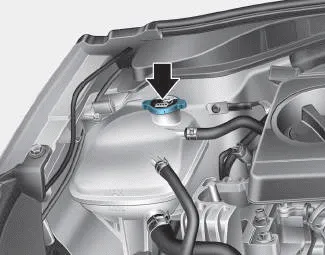
â– Type C
WARNING

Never remove the coolant cap/radiator cap or the drain plug whilst the engine and radiator are hot. Hot coolant and steam may blow out under pressure, causing serious injury.
Turn the engine off and wait until the engine cools down. Use extreme care when removing the coolant cap/radiator cap. Wrap a thick towel around it, and turn it counterclockwise slowly to the first stop. Step back whilst the pressure is released from the cooling system. When you are sure all the pressure has been released, press down on the cap, using a thick towel, and continue turning counterclockwise to remove it.
WARNING

The electric motor for the cooling fan may continue to operate or start up when the engine is not running and can cause serious injury.
Keep hands, clothing and tools away from the rotating fan blades of the cooling fan.
The electric motor for the cooling fan is controlled by engine coolant temperature, refrigerant pressure and vehicle speed. As the engine coolant temperature decreases, the electric motor will automatically shut off. This is a normal condition. If your vehicle is equipped with GDI, the electric motor for the cooling fan may begin to operate at any time and continue to operate until you disconnect the negative battery cable.
Recommended engine coolant
- When adding coolant, use only distilled (deionized) water for your vehicle and never mix hard water in the coolant filled at the factory. An incorrect coolant mixture can result in serious malfunction or engine damage.
- The engine in your vehicle has aluminium engine parts and must be protected by an ethylene-glycol with phosphate based coolant to prevent corrosion and freezing.
- DO NOT USE alcohol or methanol coolant or mix them with the specified coolant.
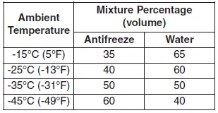
- Do not use a solution that contains more than 60% antifreeze or less than 35% antifreeze, which would reduce the effectiveness of the solution.
For mixture percentage, refer to the following table.
Information
If in doubt about the mix ratio, a 50% water and 50% antifreeze mix is the easiest to mix together as it will be the same quantity of each. It is suitable to use for most temperature ranges of -35°C (-31°F) and higher.
Changing the engine coolant
We recommend that coolant be changed by a HYUNDAI authorised repairer according to the Maintenance schedule.
NOTICE
To prevent damage to engine parts, put a thick towel around the engine coolant cap or radiator cap before refilling the coolant to prevent the coolant from overflowing into engine parts, such as the alternator.
We recommend that the engine oil and filter be replaced by a HYUNDAI authorised repairer. WARNING Used engine oil may cause irritation or cancer of the skin if left in contact with the skin for prolonged periods of time.
Checking the brake/clutch fluid level Check the fluid level in the reservoir periodically. The fluid level should be between MAX and MIN marks on the side of the reservoir.
Other information:
Hyundai i30 (PD) 2018-2024 Owner's Manual: Trailer towing equipment
Towbars Information The mounting hole for towbars are located on both sides of the underbody behind the rear tyres. It's important to have the correct towbar equipment. Crosswinds, large trucks going by, and rough roads are a few reasons why you’ll need the right towbar.
Hyundai i30 (PD) 2018-2024 Owner's Manual: Low tyre pressure telltale
Low tyre pressure telltale Low tyre pressure position telltale and tyre pressure telltale When the tyre pressure monitoring system warning indicators are illuminated and a warning message displayed on the cluster LCD display, one or more of your tyres is significantly under-inflated.
Categories
- Manuals Home
- Hyundai i30 Owners Manual
- Specifications & Consumer information
- Front fog lamp
- Engine compartment
- New on site
- Most important about car
