Hyundai i-30: Controller / Heater & A/C Control Unit (Manual)
Hyundai i30 (PD) 2018-2025 Service Manual / Heating, Ventilation and Air Conditioning / Controller / Heater & A/C Control Unit (Manual)
Components and components location
| Components |
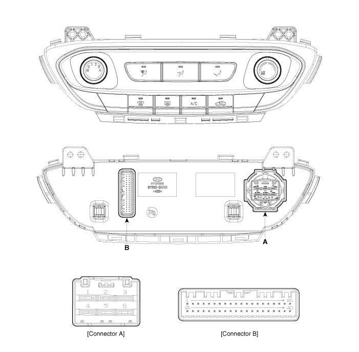
Connector [A]
|
Pin NO |
Function |
Pin NO |
Function |
|
1 |
Low |
4 |
Middle Low |
|
2 |
Common |
5 |
Middle High |
|
3 |
Ground |
6 |
High |
Connector [B]
|
Pin NO |
Function |
Pin NO |
Function |
|
1 |
Battery (+) |
21 |
IGN2 |
|
2 |
ISG B+ |
22 |
IGN1 |
|
3 |
ILL+ (TAIL) |
23 |
- |
|
4 |
Sensor REF (+5V) |
24 |
- |
|
5 |
Mode actuator feedback |
25 |
- |
|
6 |
Temperature actuator feedback |
26 |
- |
|
7 |
Intake actuator feedback |
27 |
MAX Blower ON Signal |
|
8 |
EVAP Sensor (+) |
28 |
PTC Relay 3 |
|
9 |
AMB Sensor (+) |
29 |
PTC Relay 2 |
|
10 |
Mode actuator (Vent) |
30 |
PTC on signal |
|
11 |
Mode actuator (Defrost) |
31 |
Detent OUT (-) |
|
12 |
Temperature actuator (Cool) |
32 |
- |
|
13 |
Temperature actuator (Warm) |
33 |
C_CAN High |
|
14 |
Intake actuator (Fresh Air) |
34 |
C_CAN Low |
|
15 |
Intake actuator (Recirculated Air) |
35 |
- |
|
16 |
HTD (Rear defog indicator) |
36 |
ECV + |
|
17 |
Rear defog switch |
37 |
ECV- (Ground) |
|
18 |
- |
38 |
Sensor ground |
|
19 |
Blower ON signal to common |
39 |
Ground |
|
20 |
ILL- (RHEO) |
40 |
Ground |
Repair procedures
| Replacement |
| 1. |
Disconnect the negative (-) battery terminal.
|
| 2. |
Remove the glove box upper cover assembly.
(Refer to Crash Pad - "Glove Box Upper Cover Assembly")
|
| 3. |
Remove the crash pad center lower cover (A) after loosening the mounting
screws.
|
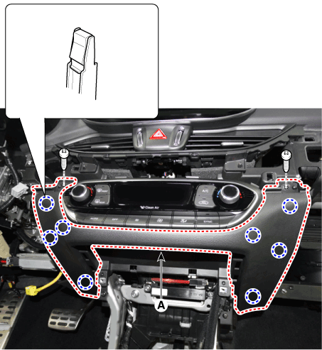
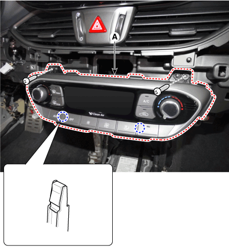
| 4. |
After loosening the mounting screws, remove the A/C & heater controller
unit (A).
|
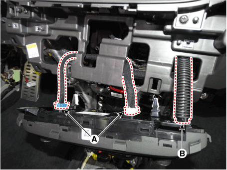
| 5. |
Disconnect the connector (A) and the air hose (B).
|
| 6. |
To install, reverse the removal procedure.
|

 Controller
..
 Heater & A/C Control Unit (DATC)
Components and components location
Components
Connector [A]
Pin NO
Function
Pin NO
Function
1
Battery (+)
21
IGN2
2
ISG B+
22
IGN1
3
ILL+ (TAIL)
23
Blower motor (+)
4
Sensor REF (+5V)
24
Photo sensor_LH
5
Mode actuator feedback
25
Photo sensor_RH
6
Temperature actuator feedback
26
-
7
Intake actuator feedback
27
-
8
EVAP Sensor (+)
28
PTC Relay 3
9
AMB Sensor (+)
29
PTC Relay 2
10
Mode actuator (Vent)
30
PTC on signal
11
Mode actuator (Defrost)
31
Detent OUT (-)
12
Temperature actuator (Cool)
32
-
13
Temperature actuator (Warm)
33
C_CAN High
14
Intake actuator (Fresh Air)
34
C_CAN Low
15
Intake actuator (Recirculated Air)
35
Power mosfet (Drain feed back)
16
HTD (Rear defog indicator)
36
Power mosfet (Gate)
17
Rear defog switch
37
ECV +
18
Clean signal
38
ECV- (Ground)
19
Ionizer diagnosis
39
Sensor ground
20
ILL- (RHEO)
40
Ground
Connector [B]
Pin NO
Function
Pin NO
Function
1
Passenger's temperature control actuator (Feedback)
9
-
2
Passenger's temperature control actuator (Cool)
10
Duct sensor (+)_Vent
3
Passenger's temperature control actuator (Warm)
11
Duct sensor (-)_Floor
4
Auto defogging (Feedback)
12
Auto defogging sensor signal
5
Auto defogging (Open)
13
-
6
Auto defogging (Off)
14
-
7
-
15
-
8
-
16
Ground
Repair procedures
Self Diagnosis
1...
Other information:
Hyundai i30 (PD) 2018-2025 Owner's Manual: Exhaust emission control system
The Exhaust Emission Control System is a highly effective system which controls exhaust emissions whilst maintaining good vehicle performance. Vehicle modifications This vehicle should not be modified. Modification of your vehicle could affect its performance, safety or durability and may even violate governmental safety and emissions regulations...
Hyundai i30 (PD) 2018-2025 Service Manual: Water pump
Repair procedures Removal and Installation • Never remove the radiator cap when the engine is hot. Serious scalding could be caused by hot fluid under high pressure escaping from the radiator...
Categories
- Manuals Home
- 3rd Generation i30 Owners Manual
- 3rd Generation i30 Service Manual
- Tyre pressure monitoring system
- Theft-alarm system
- To activate the ISG system
- New on site
- Most important about car
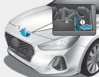
Bonnet
Opening the bonnet
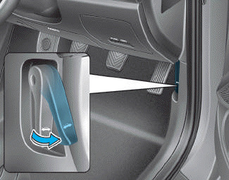
1. Park the vehicle and set the parking brake.
2. Pull the release lever to unlatch the bonnet. The bonnet should pop open slightly.

Copyright © 2025 www.hi30.net