Hyundai i30 (PD): Exterior features / Bonnet
Opening the bonnet

1. Park the vehicle and set the parking brake.
2. Pull the release lever to unlatch the bonnet. The bonnet should pop open slightly.
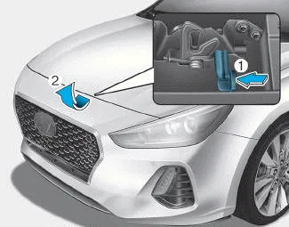
3. Go to the front of the vehicle, raise the bonnet slightly, push the secondary latch up (1) inside of the bonnet centre and lift the bonnet (2).
4. Pull out the support rod.
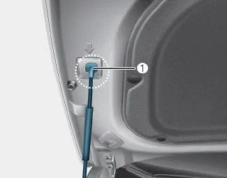
5. Hold the bonnet open with the support rod (1).
WARNING
- Grasp the support rod in the area wrapped in rubber. The rubber will help prevent you from being burned by hot metal when the engine is hot.
- The support rod must be inserted completely into the hole provided whenever you inspect the engine compartment. This will prevent the bonnet from falling and possibly injuring you.
Closing the bonnet
1. Before closing the bonnet, check the following:
- All filler caps in engine compartment must be correctly installed.
- Gloves, rags or any other combustible material must be removed from the engine compartment.
2. Return the support rod to its clip to prevent it from rattling.
3. Lower the bonnet halfway (lifted approximately 30cm from the closed position) and push down to securely lock in place. Then double check to be sure the bonnet is secure.
If the bonnet can be raised slightly, it is not securely locked. Open it again and close it with more force.
WARNING
- Before closing the bonnet, ensure all obstructions are removed from around the bonnet opening.
- Always double check to be sure that the bonnet is firmly latched before driving away. Check there is no bonnet open warning light or message displayed on the instrument cluster. If the bonnet is not latched whilst the vehicle is moving, the chime will sound to warn the driver the bonnet is not fully latched. Driving with the bonnet opened may cause a total loss of visibility, which might result in an accident.
- Do not move the vehicle with the bonnet in the raised position, as vision is obstructed, which might result in an accident, and the bonnet could fall or be damaged.
Opening the tailgate â– 5 Door, Wagon â– Fastback Make sure the vehicle is in P (Park) and set the parking brake. Then do one of the following: 1.
Other information:
Hyundai i30 (PD) 2018-2024 Owner's Manual: Maintenance services
You should exercise the utmost care to prevent damage to your vehicle and injury to yourself whenever performing any maintenance or inspection procedures. We recommend you have your vehicle maintained and repaired by a HYUNDAI authorised repairer.
Hyundai i30 (PD) 2018-2024 Owner's Manual: Fuel filter (for diesel)
Draining water from fuel filter The fuel filter in the diesel engine operates the critical function of separating water from the fuels and preventing accumulating of water in the base. When enough water is accumulated inside the fuel filter, the warning light () illuminates with the ignition switch in the ON position.
Categories
- Manuals Home
- Hyundai i30 Owners Manual
- Exhaust System (DPF) Warning Light. Glow Indicator Light
- Headlamp, static bending lamp, position lamp, turn signal lamp and daytime running light bulb replacement
- Your vehicle at a glance
- New on site
- Most important about car
