Hyundai i-30: IMS(Integrated Memory System) / Memory power seat switch
Hyundai i30 (PD) 2018-2025 Service Manual / Body Electrical System / IMS(Integrated Memory System) / Memory power seat switch
Components and components location
| Components |
Repair procedures
| Removal |
| 1. |
Disconnect the negative (-) battery terminal.
|
| 2. |
Remove the driver door trim.
(Refer to Body - "Front Door Trim")
|
| 3. |
Disconnect the memory power seat switch connector (A).
|
| 4. |
Remove the memory power switch (A) after disengaging the mounting screws.
|
| Installation |
| 1. |
Install the memory power seat control switch (IMS).
|
| 2. |
Install the door trim.
|
| 3. |
Connect the negative (-) battery terminal.
|
| Inspection |
| 1. |
Remove the memory power seat connector
|
| 2. |
When each switch is pressed, check the electricity flow between memory
power seat switch connector and grounding, and if the electricity does
not match the specification, replace the switch.
|
 Memory power seat unit
Components and components location
Components
No
Connecter A
Connecter B
Connecter C
1
-
Battery (+)
Slide switch (Forward)
2
Reclining motor (Forward)
GND
Reclining switch (Forward)
3
Height motor (Up)
Battery (+)
Tilt switch (Up)
4
Slide motor (Forward)
-
Height switch (Up)
5
-
GND
-
6
Reclining motor (Backward)
B-CAN (High)
7
Tilt motor (Up)
B-CAN (High)
8
Tilt motor (Down)
IMS Switch 1
9
Height motor (Down)
Reclining switch (Forward)
10
Slide motor (Backward)
Slide sensor
11
Tilt sensor
12
-
13
Position sensor (Power)
14
IGN 1
15
Seat back slide switch (Forward)
16
Seat back reclining switch (Forward)
17
Tilt switch (Down)
18
Height switch (Down)
19
-
20
Ground
21
SET Switch
22
IMS Switch 2
23
Seat back limit switch (Backward)
24
Seat Reclining sensor
25
Seat height sensor
26
-
27
-
28
Battery (+)
Schematic diagrams
Circuit Diagram
Repair procedures
Removal
1...

Other information:
Hyundai i30 (PD) 2018-2025 Service Manual: Rain Sensor
Components and components location Components and Components Location Schematic diagrams Circuit Diagram Description and operation Description Integrated Rain Sensor Integrated rain sensor (A) controls three systems: front wiper, auto-light, and central air conditioner...
Hyundai i30 (PD) 2018-2025 Service Manual: Rear Door Inside Handle
Repair procedures Replacement 1. Remove the rear door trim. (Refer to Rear Door - "Rear Door Trim") 2. After loosening the mounting screws, remove the rear door inside handle (A)...
Categories
- Manuals Home
- 3rd Generation i30 Owners Manual
- 3rd Generation i30 Service Manual
- Recommended lubricants and capacities
- Front windscreen wiper service position
- Battery replacement
- New on site
- Most important about car
Air bag - supplemental restraint system
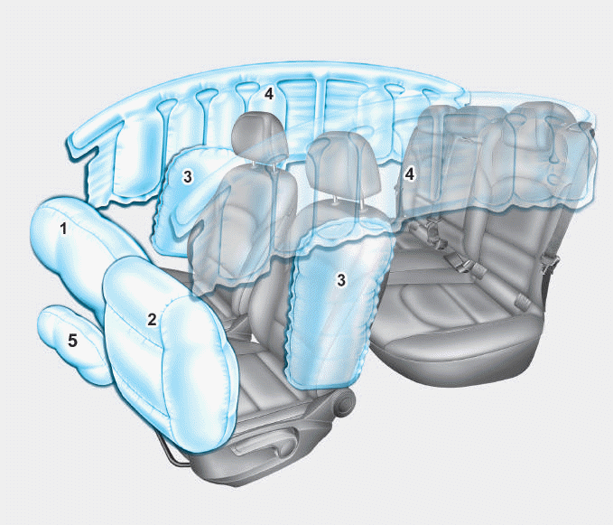
1. Driver’s front air bag
2. Passenger’s front air bag
3. Side air bag*
4. Curtain air bag*
5. Knee air bag*
6. Front passenger air bag ON/OFF
switch

Copyright © 2025 www.hi30.net