Hyundai i-30: BCM (Body Control Module) / Repair procedures
Hyundai i30 (PD) 2018-2025 Service Manual / Body Electrical System / BCM (Body Control Module) / Repair procedures
| Removal |
| 1. |
Disconnect the negative (-) battery terminal.
|
| 2. |
Remove the glove box upper cover assembly.
(Refer to Body - "Glove Box Upper Cover Assembly")
|
| 3. |
Remove the smart key unit.
(Refer to -"Smart Key Unit")
|
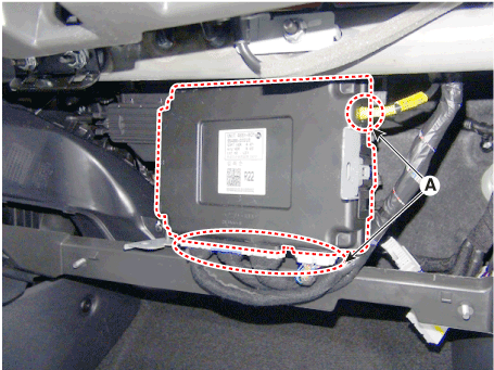
| 4. |
Remove the body control module (A) after loosening the mounting nuts
and screw.
|
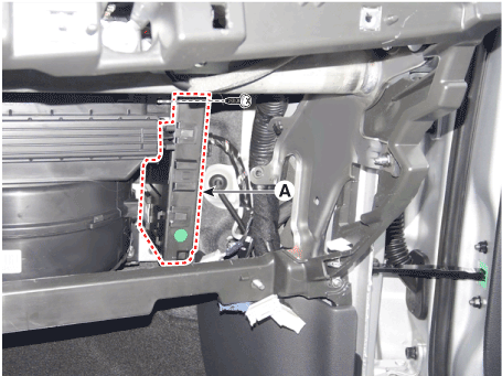
| 5. |
Remove the body control module (B) after disconnecting the connector
(A).
|
| Installation |
| 1. |
Install the body control module (BCM).
|
| 2. |
Install the smart key unit (SMK).
|
| 3. |
Install the glove box upper cover assembly.
|
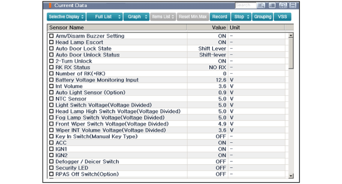
| BCM Diagnosis With GDS |
| 1. |
In the body electrical system, failure can be quickly diagnosed by using
the vehicle diagnostic system (GDS).
The diagnostic system (GDS) provides the following information.
|
| 2. |
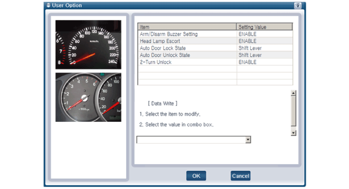
Select the "Car model" and the 'Body Control Module (BCM)' to be checked
in order to check the vehicle with the tester.
|
| 3. |
Select the 'Current Data' menu to search the current state of the input/output
data.
|
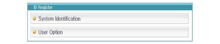
| 4. |
If you want to change user option, select "user option".
|
 Description and operation
Description
Body Control Module (BCM) function
No
Item
Description
1
Washer Linked Wiper
–
If the washer switch is pressed ON for 0...

Other information:
Hyundai i30 (PD) 2018-2025 Owner's Manual: Wheel alignment and tyre balance
The wheels on your vehicle were aligned and balanced carefully at the factory to give you the longest tyre life and best overall performance. In most cases, you will not need to have your wheels aligned again. However, if you notice unusual tyre wear or your vehicle pulling one way or the other, the alignment may need to be reset...
Hyundai i30 (PD) 2018-2025 Service Manual: Components and components location
..
Categories
- Manuals Home
- 3rd Generation i30 Owners Manual
- 3rd Generation i30 Service Manual
- FCA sensor
- Recommended lubricants and capacities
- Headlamp, static bending lamp, position lamp, turn signal lamp and daytime running light bulb replacement
- New on site
- Most important about car
Turn signals and lane change signals
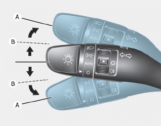
To signal a turn, push down on the lever for a left turn or up for a right turn in position (A). To signal a lane change, move the turn signal lever slightly and hold it in position (B).The lever will return to the OFF position when released or when the turn is completed.

Copyright © 2025 www.hi30.net