Hyundai i-30: Seat Electrical / Power Seat Control Switch
Hyundai i30 (PD) 2018-2025 Service Manual / Body Electrical System / Seat Electrical / Power Seat Control Switch
Schematic diagrams
| Circuit Diagram |
[Driver power seat switch]
Repair procedures
| Inspection |
Seat Control Switch
| 1. |
With the power seat switch in each position, make sure that continuity
exists between the terminals below. If continuity is not as specified,
replace the power seat switch.
[Power seat control switch]
|
| Removal |
| 1. |
Disconnect the negative (-) battery terminal.
|
| 2. |
Remove the front seat outer shield cover.
(Refer to Body - "Front Seat Outer Shield Cover")
|
| 3. |
Remove the power seat control switch (A) after loosening the screws.
|
| Installation |
| 1. |
Install the power seat control switch after connecting the connector.
|
| 2. |
Install the front seat outer shield cover.
|
| 3. |
Connect the negative (-) battery terminal.
|
 Power Seat Motor
Components and components location
Component Location
1. Lumber support
motor (Horizontal)
2. Rear height motor
3...
 Seat Heater
Components and components location
Component Location
Front Seat Heater
1. Seat heater
unit (Assist seat only)
2...
Other information:
Hyundai i30 (PD) 2018-2025 Owner's Manual: Additional seat belt safety precautions
Seat belt use during pregnancy The seat belt should always be used during pregnancy. The best way to protect your unborn child is to protect yourself by always wearing the seat belt. Pregnant women should always wear a lap-shoulder seat belt...
Hyundai i30 (PD) 2018-2025 Owner's Manual: Automatic climate control system
1. Passenger’s temperature control knob 2. Driver’s temperature control knob 3. SYNC button 4. OFF button 5. Fan speed control button 6. Mode selection button 7. AUTO (automatic control) button 8. Air conditioning button 9. Air intake control button 10...
Categories
- Manuals Home
- 3rd Generation i30 Owners Manual
- 3rd Generation i30 Service Manual
- Theft-alarm system
- FCA sensor
- Exhaust System (DPF) Warning Light. Glow Indicator Light
- New on site
- Most important about car
Turn signals and lane change signals
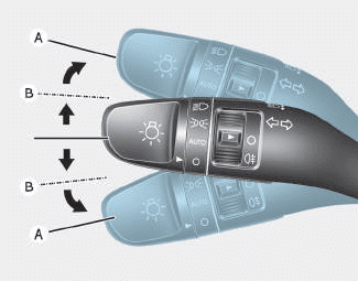
To signal a turn, push down on the lever for a left turn or up for a right turn in position (A). To signal a lane change, move the turn signal lever slightly and hold it in position (B).The lever will return to the OFF position when released or when the turn is completed.

Copyright © 2025 www.hi30.net