Hyundai i-30: Rear Door / Rear Door Module
Hyundai i30 (PD) 2018-2025 Service Manual / Body (Interior and Exterior) / Rear Door / Rear Door Module
Components and components location
| Component Location |
| 1. Rear door
module |
Repair procedures
| Replacement |
| 1. |
Remove the rear door window glass.
(Refer to Rear Door - "Rear Door Window Glass")
|
| 2. |
Remove the rear door outside handle.
(Refer to Rear Door - "Rear Door Outside Handle")
|
| 3. |
Thereby releasing the rear door clearance channel mounting bolt and
nuts.
|
| 4. |
Remove the rear door channel (A).
|
| 5. |
Loosen the rear door outside handle base mounting screw (A).
|
| 6. |
Loosen the rear door latch mounting screws (A).
|
| 7. |
Remove the rear door module wiring cover (A).
|
| 8. |
Disconnect the rear door main connector (A).
|
| 9. |
After loosening the mounting bolts, remove the rear door module (A).
|
| 10. |
Disconnect the rear door main wiring (A).
|
| 11. |
Remove the rear door latch assembly.
(Refer to Front Door - "rear Door Latch")
|
| 12. |
Reomove the rear speaker.
(Refer to Body Electrical System - "Speakers")
|
| 13. |
Remove the rear power window motor.
(Refer to Body Electrical System - "Power Window Motor")
|
| 14. |
To install, reverse removal procedure.
|

 Rear Door Window Glass
Components and components location
Component Location
1. Rear door
window glass
Repair procedures
Replacement
1...
 Rear Door Outside Handle
Components and components location
Component Location
1. Rear door
outside handle
Repair procedures
Replacement
1...
Other information:
Hyundai i30 (PD) 2018-2025 Service Manual: Intercooler
Components and components location Comoinents 1. Intercooler assembly 2. Intercooler air guard 3. Intercooler inlet hose & pipe 4. Intercooler outlet hose & pipe 5. RCV solenoid hose B 6...
Hyundai i30 (PD) 2018-2025 Owner's Manual: Suitability of each seating position for ISOFIX Child Restraint Systems according to ECE regulations - 5 Door,Wagon
IUF = Suitable for ISOFIX forward child restraints systems of universal category approved for use in the mass group. IL = Suitable for particular ISOFIX child restraints systems (CRS) given in the attached list. These ISOFIX CRS are those of the "specific vehicle", "restricted" or "semi-universal" categories...
Categories
- Manuals Home
- 3rd Generation i30 Owners Manual
- 3rd Generation i30 Service Manual
- Front windscreen wiper service position
- Engine coolant
- Battery replacement
- New on site
- Most important about car
Seat belt warning light
Seat belt warning
Driver’s seat belt warning
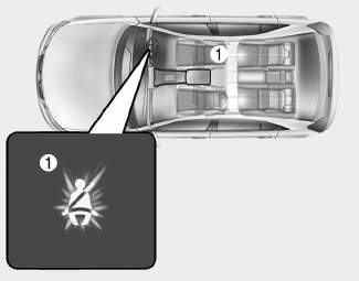
■ Instrument cluster
As a reminder to the driver, the seat belt warning light will illuminate for approximately 6 seconds each time you turn the ignition switch ON regardless of belt fastening.

Copyright © 2025 www.hi30.net