Hyundai i-30: Clutch Pedal / Repair procedures
[Manual Transaxle Type]
1. |
Turn ignition switch OFF and disconnect the negative (-) battery cable.
|
2. |
Remove the clutch master cylinder.
(Refer to Clutch System - "Cluch Master Cylinder")
|
3. |
Remove the crash pad lower panel.
(Refer to Body - "Crash Pad Lower Panel")
|
4. |
Remove the junction box (passenger compartment).
(Refer to Body Electrical System - "Fuses And Relays")
|
5. |
Remove the knee air bag module.
(Refer to Restraint (Airbag(Event #1)) - "Knee Airbag (KAB) Module")
|
6. |
Disconnect the clutch & ignition lock switch connector (A).
|
7. |
Loosen the mounting nuts (A) and then removing the cluch pedal assembly
(B).
Tightening torque :
16.7 - 25.5 N.m (1.7 - 2.6 kgf.m, 12.3 - 18.8 Ib-ft)
|
|
[Intelligent Manual Transaxle Type]
1. |
Turn ignition switch OFF and disconnect the negative (-) battery cable.
|
2. |
Remove the crash pad lower panel.
(Refer to Body - "Crash Pad Lower Panel")
|
3. |
Remove the junction box (passenger compartment).
(Refer to Body Electrical System - "Fuses And Relays")
|
4. |
Remove the knee air bag module.
(Refer to Restraint (Airbag(Event #1)) - "Knee Airbag (KAB) Module")
|
5. |
Remove the TCM.
(Refer to Intelligent Manual Transaxle (IMT) System (Intelligent Manual
Transmission) - IMT Control Module (TCM))
|
6. |
Disconnect the stroke sensor connector (A) and the clutch & ignition
lock switch connector (B).
|
7. |
Loosen the mounting nuts (A) and then removing the cluch pedal assembly
(B).
Tightening torque :
16.7 - 25.5 N.m (1.7 - 2.6 kgf.m, 12.3 - 18.8 Ib-ft)
|
|
1. |
To install, reverse the removal procedures.
|
2. |
Perform bleeding air procedure in concentric slave cylinder after pouring
the brake fluid.
(Refer to Clutch System - "Concentric Slave Cylinder Assembly")
|
Components
[Manual Transaxle Type]
1. Clutch pedal assembly
2. Clutch pedal arm
3. Ignition lock & clutch switch
4...
Other information:
Component Location Index
Engine Room
1. Expansion
valve
2. Service port (Low pressure)
3. Service port (High pressure)
4. A/C Pressure transducer (APT)
5. Compressor
6. Discharge
hose
7. Suction & Liquid tube assembly
8...
Schematic diagrams
ECM Terminal and Input /
Output signal
ECM Harness Connector
ECM Terminal Function
Connector [A]
Terminal
Description
1
Fuel Pressure Regulator Valve (FPRV) [High] Control
2
Integrated Thermal Management Module (ITM) Motor (+)
3
Integrated Thermal Management Module (ITM) Motor (-)
4
Exhaust Gas Temperature Sensor (EGTS) #2 (T4) Ground [GPF Type]
5
Engine Coolant Temperature Sensor (ECTS) #1 Ground
6
-
7
Engine Coolant Temperature Sensor (ECTS) #2 Ground
8
Differential Pressure Valve (DPV) Ground
9
Rail Pressure Sensor (RPS) Ground
10
Exhaust Gas Temperature Sensor (EGTS) Ground
11
Manifold Absolute Pressure Sensor (MAPS) Ground
12
Electric Waste Gate Control Actuator (EWGA) Ground
13
EGR Pressure Sensor Ground
14
Oil Pressure & Temperature Sensors (OPTS) Ground
15
Electric Exhaust Gas Recirculation (EEGR) Control Valve Ground
16
-
17
A/C Pressure Transducer (APT) Ground
18
Sensor Power (+5V) (Camshaft Position Sensor (CMPS) [Bank 1 / Intake, Exhaust])
19
Sensor Power (+5V) (Manifold Absolute Pressure Sensor (MAPS))
Sensor Power (+5V) (Electric Exhaust Gas Recirculation (EEGR))
Sensor Power (+5V) (Crankshaft Position Sensor (CKPS))
20
Sensor Power (+5V) (Oil Pressure & Temperature Sensors (OPTS))
Sensor Power (+5V) (Electric Throttle Control Module (ETC))
Sensor Power (+5V) (Rail Pressure Sensor (RPS))
21
Throttle Position Sensor (TPS) Ground
22
Electric Exhaust Gas Recirculation (EEGR) Control Valve Motor (+)
23
Electric Exhaust Gas Recirculation (EEGR) Control Valve Motor (-)
24
Knock Sensor (KS ) Shield Ground
25
-
26
Ignition Coil (Cylider #3) Control
27
-
28
-
29
Exhaust Gas Temperature Sensor (EGTS) #1 (T3) Ground [GPF Type]
30
-
31
-
32
-
33
EGR Pressure Sensor Signal
34
-
35
Integrated Thermal Management Module (ITM) Motor Ground
36
-
37
Camshaft Position Sensor (CMPS) [Bank 1 / Intake] Signal
38
-
39
Electric Waste Gate Control Actuator (EWGA) Signal
40
Sensor Power (+5V) (EGR Pressure Sensor)
Sensor Power (+5V) (Electric Waste Gate Control Actuator (EWGA))
41
Sensor Power (+5V) (Accelerator Position Sensor (APS #1))
42
Sensor Power (+5V) (Brake Booster Vacuum Pressure Sensor (BBVPS))
Sensor Power (+5V) (A/C Pressure Transducer (APT))
43
Injector (Cylinder #3) [+] Control
44
Injector (Cylinder #2) [+] Control
45
-
46
-
47
CCP-CAN [High]
48
Ignition Coil (Cylinder #1) Control
49
-
50
Neutral Switch [With ISG]
51
-
52
-
53
-
54
Exhaust Gas Temperature Sensor (EGTS) #1 (T3) Signal [GPF Type]
55
-
56
Exhaust Gas Temperature Sensor (EGTS) #2 (T4) Signal [GPF Type]
57
-
58
Differential Pressure Sensor (DPS) Signal
59
Exhaust Gas Temperature Sensor (EGTS) Signal
60
Camshaft Position Sensor (CMPS) [Bank 1 / Exhaust] Ground
61
Mass Air Flow Sensor (MAFS) Signal
62
-
63
Engine Speed Signal Output
64
Injector (Cylinder #1) [+] Control
65
Injector (Cylinder #4) [+] Control
66
Injector (Cylinder #3) [-] Control
67
Injector (Cylinder #4) [-] Control
68
Ignition Coil (Cylider #2) Control
69
CCP-CAN [Low]
70
Camshaft Position Sensor (CMPS) [Bank 1 / Exhaust] Signal
71
Crankshaft Position Sensor (CKPS) Ground
72
Ignition Lock Switch [M/T & Without Smart Key]
73
Oil Pressure Sensor (OPS) Signal
74
Intake Air Temperature Sensor (IATS) Signal
75
Engine Coolant Temperature Sensor (ECTS) #1 Signal
76
Engine Coolant Temperature Sensor (ECTS) #2 Signal
77
Electric Exhaust Gas Recirculation (EEGR) Control Valve Signal
78
Differential Pressure Valve (DPV) Signal
79
Throttle Position Sensor (TPS) #2 Signal
80
Rail Pressure Sensor (RPS) Signal
81
-
82
Integrated Thermal Management Module (ITM) Motor Signal
83
Mass Air Flow Sensor (MAFS) Ground
84
A/C Pressure Transducer (APT) Signal
85
-
86
Injector (Cylinder #2) [-] Control
87
Injector (Cylinder #1) [-] Control
88
Fuel Pressure Regulator Valve (FPRV) [Low] Control
89
Differential Pressure Sensor (DPS) Ground
90
Ignition Coil (Cylinder #4) Control
91
Crankshaft Position Sensor (CKPS) Signal
92
-
93
Heated Oxygen Sensor (HO2S) [Bank 1 / Sensor 2] Ground
94
-
95
Heated Oxygen Sensor (HO2S) [Bank 1 / Sensor 2] Signal
96
-
97
Oil Temperature Sensor (OTS) Signal
98
Throttle Position Sensor (TPS) #1 Signal
99
-
100
-
101
Manifold Absolute Pressure Sensor (MAPS) Signal
102
Camshaft Position Sensor (CMPS) [Bank 1/Intake] Ground
103
-
104
Knock Sensor (KS) Signal
105
Knock Sensor (KS) Ground
Connector [B]
Terminal
Description
1
Chassis Ground
2
Chassis Ground
3
Battery Power (B+) (Battery)
4
Chassis Ground
5
Battery Power (B+) (Main Relay)
6
Battery Power (B+) (Main Relay)
7
-
8
-
9
Sensor Power (+5V) (Integrated Thermal Management Module (ITM) Motor)
Sensor Power (+5V) (Mass Air Flow Sensor (MAFS))
10
Sensor Power (+5V) (Accelerator Position Sensor (APS) #2)
11
Boost Pressure Sensor (BPS) Signal Input
12
Accelerator Position Sensor (APS) #2 Ground
13
Accelerator Position Sensor (APS) #1 Ground
14
Brake Booster Vacuum Pressure Sensor (BBVPS) Ground [With ISG]
15
-
16
Boost Pressure Sensor (BPS) Ground
17
Fuel Level Sender (FLS) Signal
18
Accelerator Position Sensor (APS #2) Signal
19
-
20
-
21
-
22
RCV Control Solenoid Valve Control
23
Cooling Fan Relay [PWM] Control
24
Electric Waste Gate Control Actuator (EWGA) DC Motor (+) Control
25
Electric Waste Gate Control Actuator (EWGA) DC Motor (-) Control
26
Ignition Switch Signal Input
27
Sensor Power (+5V) (Differential Pressure Sensor (DPS))
Sensor Power (+5V) (Differential Pressure Valve (DPV))
Sensor Power (+5V) (Boost Pressure Sensor (BPS))
28
-
29
-
30
Brake Light Switch Signal Input
31
Brake Test Switch Signal Input
32
Accelerator Position Sensor (APS #1) Signal
33
-
34
ISG OFF Switch Signal Input [With ISG]
35
Start Signal Input
36
-
37
Fuel Pump Relay Control [W/O Smart Key]
38
DC/DC Converter (LDC) Control [With ISG]
39
-
40
Variable Oil Pump Valve Control
41
ETC Motor [+] Control
42
ETC Motor [-] Control
43
-
44
LIN communication signal input
45
C-CAN (Low)
46
-
47
-
48
Clutch Switch [M/T]
49
Wiper Switch Signal Input
50
Blower Motor MAX Input
51
Start Relay Control (Low Side)
52
-
53
-
54
Rear Defrost Switch Signal Input
55
-
56
-
57
-
58
Differential Pressure Valve (DPV) DC Motor (+) Control
59
Differential Pressure Valve (DPV) DC Motor (-) Control
60
Battery Power (B+) (Battery)
61
LIN Communication Signal input
62
C-CAN (High)
63
Brake Booster Vacuum Pressure Sensor (BBVPS) Signal [With ISG]
64
Heated Oxygen Sensor (HO2S) [Bank 1 / Sensor 1] VS+ (NERNST Cell Voltage)
65
Heated Oxygen Sensor (HO2S) [Bank 1 / Sensor 1] Rc (Compensative Resistance)
66
Heated Oxygen Sensor (HO2S) [Bank 1 / Sensor 1] Rc/Rp (Pump Cell Voltage)
67
Heated Oxygen Sensor (HO2S) [Bank 1 / Sensor 1] VS-/IP- (Common Ground for
VS, IP)
68
-
69
A/C Compressor Relay Control
70
-
71
Start Relay Control (High side)
72
-
73
-
74
Engine Control Relay Control
75
Heated Oxygen Sensor (HO2S) [Bank 1 / Sensor 1] Heater Control
76
Heated Oxygen Sensor (HO2S) [Bank 1 / Sensor 2] Heater Control
77
Vehicle Speed Signal Input
78
CCP-CAN [High]
79
CCP-CAN [Low]
80
-
81
-
82
-
83
Purge Control Solenoid Valve (PCSV) Control
84
Fuel Pump Relay Control [With Smart Key]
85
ISG OFF Switch (IND...
Categories
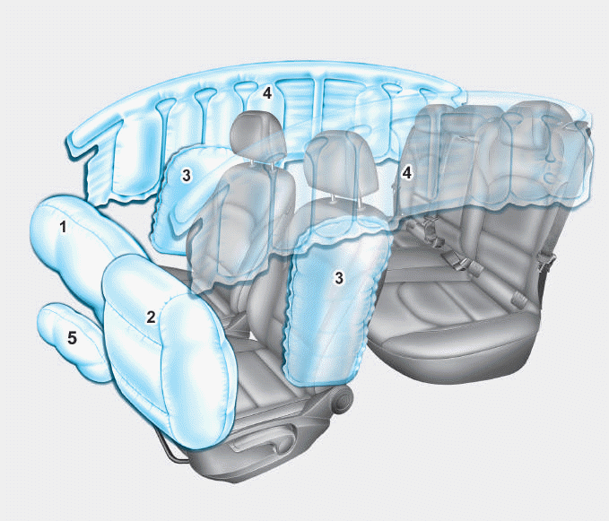
1. Driver’s front air bag
2. Passenger’s front air bag
3. Side air bag*
4. Curtain air bag*
5. Knee air bag*
6. Front passenger air bag ON/OFF
switch
read more