Hyundai i-30: Brake System / Stop Lamp Switch
Components and components location
| Components |
| 1. Brake member
assembly 2. Stop lamp switch 3. Return spring |
4. Brake pedal
arm assembly 5. Brake pedal pad |
Schematic diagrams
| Schematic Diagram |
| System Circuit Diagram |
| Terminal Function |
|
Teminal |
Description |
|
1 |
IGN1 |
|
2 |
BS |
|
3 |
- |
|
4 |
B+ |
|
5 |
Stop Lamp |
|
6 |
Ground |
Troubleshooting
| Troubleshooting |
| 1. |
Part diagnosis
|
| 2. |
Symptom diagnosis
|
| 3. |
Stop lamp switch system diagnosis
SSEM : Stop Signal Electronic Module
|
| 4. |
Refer to DTC guide when the related DTC codes are displayed.
|
Repair procedures
| Adjustment |
| 1. |
Turn ignition switch OFF and disconnect the negative (-) battery cable.
|
| 2. |
Remove the lower crash pad.
(Refer to Body - "Crash Pad")
|
| 3. |
Confirm the gap between stop lamp switch and bracket.
|
| 4. |
If the gap between stop lamp switch and bracket is not 1.0-2.0mm (0.04-0.08in),
check the mounting clip and other part of around stop lamp.
|
| 5. |
If there is normal, remove the stop lamp switch and then install again.
|
| Inspection |
1. Fuse Inspection
Mount the test fuse to the switch fuse and relay fuse part to confirm a normal
joint fit.
2. Diagnostic tool Data Analysis
| 1. |
Analyze diagnostic tool data and confirm if there is anything wrong
with the stop lamp switch.
|
3. Inspection Of Connector By Each Part
Check to see whether or not each connector has been damaged, or terminal surge,
or incomplete connection has taken place
[Engine Room Junction Box]
[ABS/VDC Control Module]
4. Inspect The Stop Lamp Circuit
Connect probe to each terminal wire and confirm oscilloscope waveform.
[Stop Lamp Switch Input / Output]
[Oscilloscope Waveform Screen]
| Removal |
| 1. |
Turn ignition switch OFF and disconnect the negative (-) battery cable.
|
| 2. |
Remove the crash pad lower panel.
(Refer to Body - "Crash Pad Lower Panel")
|
| 3. |
Disconnect the stop lamp switch connector (A).
|
| 4. |
Pull the locking plate (A) as indicated by the arrow.
|
| 5. |
Turn stop lamp switch 45° counterclockwise and remove it.
|
| 6. |
Inspect a removed stop lamp switch along the below procedures.
|
| Installation |
| 1. |
Fix the brake pedal arm and insert fully the stop lamp switch as hiding
contact part.
|
| 2. |
After inserting, turn the stop switch (A) 45° clockwise, and then assemble
locking plate by pushing.
|
| 3. |
Confirm the gap between stop lamp switch and bracket.
|

| 4. |
Connect the stop lamp switch connector.
|
| 5. |
Install the crash pad lower panel.
(Refer to Body - "Crash Pad Lower Panel")
|
 Rear Disc Brake
Components and components location
Components
[With EPB]
1. Caliper body
2. Guide rod pin
3. Guide rod pin boot
4...

Other information:
Hyundai i30 (PD) 2018-2025 Service Manual: Steering Column Shroud Panel
Components and components location Component Location 1. Steering column shroud lower panel 2. Steering column shroud upper panel Repair procedures Replacement [Steering column shroud upper panel] • Put on gloves to prevent hand injuries...
Hyundai i30 (PD) 2018-2025 Service Manual: Blower Motor
Repair procedures Inspection 1. Connect the battery voltage and check the blower motor rotation. 2. If the blower motor does not operate well, substitute with a known-good blower motor and check for proper operation...
Categories
- Manuals Home
- 3rd Generation i30 Owners Manual
- 3rd Generation i30 Service Manual
- EPB malfunction indicator
- Cruise control
- To activate the ISG system
- New on site
- Most important about car
Tailgate
Opening the tailgate
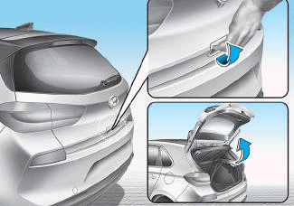
■ 5 Door, Wagon
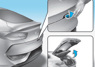
■ Fastback

Copyright © 2025 www.hi30.net