Hyundai i-30: Engine Control System / Accelerator Position Sensor (APS)
Hyundai i30 (PD) 2018-2025 Service Manual / Engine Control / Fuel System / Engine Control System / Accelerator Position Sensor (APS)
Description and operation
| Description |
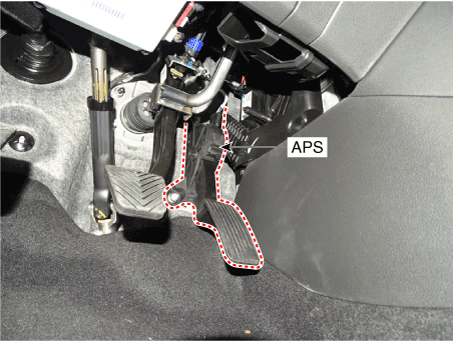
Accelerator Position Sensor (APS) is installed on the accelerator pedal module
and detects the rotation angle of the accelerator pedal. The APS is one of the
most important sensors in engine control system, so it consists of the two sensors
which adapt individual sensor power and ground line. The second sensor monitors
the first sensor and its output voltage is half of the first one. If the ratio
of the sensor 1 and 2 is out of the range (approximately 1/2), the diagnostic
system judges that it is abnormal.
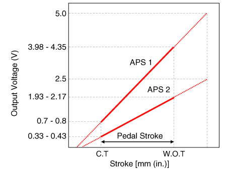
Specifications
| Specification |
|
Accelerator Position |
Output Voltage (V) |
|
|
APS1 |
APS2 |
|
|
C.T |
0.7 - 0.8 |
0.325 - 0.425 |
|
W.O.T |
3.98 - 4.22 |
1.93 - 2.17 |
Schematic diagrams
| Circuit Diagram |
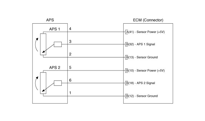
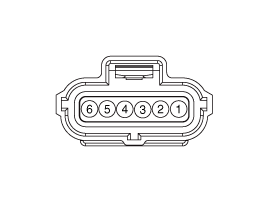
Harness Connector
Repair procedures
| Inspection |
| 1. |
Connect the diagnostic tool to the Data Link Connector (DLC).
|
| 2. |
Turn the ignition switch ON.
|
| 3. |
Measure the output voltage of the APS 3 and 6 at C.T and W.O.T.
|
 Heated Oxygen Sensor (HO2S)
Description and operation
Description
Heated Oxygen Sensor (HO2S) consists of zirconium and alumina and is installed
both upstream and downstream of the Manifold Catalytic Converter...
 Rail Pressure Sensor (RPS)
Description and operation
Description
Rail Pressure Sensor (RPS) is installed on the delivery pipe and measures the
instantaneous fuel pressure in the delivery pipe...
Other information:
Hyundai i30 (PD) 2018-2025 Service Manual: Injector
Description and operation Description The GDI injector is similar to a standard injector, but sprays fuel at a much higher pressure directly into the combustion chamber and has a swirl disc to get the fuel swirling as it exits the nozzle...
Hyundai i30 (PD) 2018-2025 Service Manual: Troubleshooting
Basic Troubleshooting Basic Troubleshooting Guide Customer Problem Analysis Sheet Basic Inspection Procedure Measuring Condition of Electronic Parts' Resistance The measured resistance at high temperature after vehicle running may be high or low...
Categories
- Manuals Home
- 3rd Generation i30 Owners Manual
- 3rd Generation i30 Service Manual
- Headlamp, static bending lamp, position lamp, turn signal lamp and daytime running light bulb replacement
- Trip computer
- Theft-alarm system
- New on site
- Most important about car
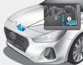
Bonnet
Opening the bonnet
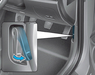
1. Park the vehicle and set the parking brake.
2. Pull the release lever to unlatch the bonnet. The bonnet should pop open slightly.

Copyright © 2025 www.hi30.net