Hyundai i-30: Engine and Transaxle Assembly / Engine and Transaxle Assembly
Hyundai i30 (PD) 2018-2025 Service Manual / Engine Mechanical System / Engine and Transaxle Assembly / Engine and Transaxle Assembly
Repair procedures
| Removal |
|

|

| 1. |
Disconnect the battery negative terminal.
|
| 2. |
Remove the engine cover.
(Refer to Engine and Transaxle Assembly - "Engine Cover")
|
| 3. |
Remove the air duct and air cleaner assembly.
(Refer to Intake and Exhasut System - "Air Cleaner")
|
| 4. |
Remove the battery.
(Refer to Engine Electrical System - "Battery")
|
| 5. |
Remove the engine control module (ECM).
(Refer to Engine Control / Fuel System - "Engine Control Module (ECM)")
|
| 6. |
Remove the battery tray.
(Refer to Engine Electrical System - "Battery")
|
| 7. |
Remove the engine room under cover.
(Refer to Engine and Transaxle Assembly - "Engine Room Under Cover")
|
| 8. |
Drain the engine coolant.
(Refer to Cooling System - "Coolant")
|
| 9. |
Disconnect the radiator upper hose (A).
|
| 10. |
Disconnect the radiator lower hose (A).
|
| 11. |
Disconnect the fuel hose (A) and the purge control solenoid valve (PCSV)
hose (B).
|
| 12. |
Disconnect the reservoir tank water hoses (A).
|
| 13. |
Disconnect the brake booster vacuum hose (A) and the heater hoses (B).
|
| 14. |
Remove the intercooler outlet hose and pipe.
|
| 15. |
Disconnect the wiring harness from the engine room.
|
| 16. |
Remove the transaxle wire harness connectors and control cable from
the transaxle.
(Refer to Double Clutch Transmission (DCT) System - "Double Clutch Control
System")
|
| 17. |
Recover the refrigerant and then remove the high pressure pipe and low
pressure pipe.
(Refer to Heating, Ventilation Air conditioning - "Compressor")
|
| 18. |
Remove the front muffler.
(Refer to Intake and Exhaust System - "Muffler")
|
| 19. |
Remove the intercooler inlet hose and pipe.
|
| 20. |
Remove the steering U-joint mounting bolt.
(Refer to Steering System - "Steering Column and Shaft")
|
| 21. |
Remove the roll rod bracket (A).
|
| 22. |
Remove the roll rod mounting support bracket (A).
|
| 23. |
Remove the sub frame.
(Refer to Suspension System - "Sub Frame")
|
| 24. |
Disconnect the engine ground cable (A).
|
| 25. |
Remove the engine mounting support bracket (A).
|
| 26. |
Disconnect the transaxle ground cable (A).
|
| 27. |
Remove the front wheel guard.
(Refer to Body - "Body Side Molding")
|
| 28. |
Remove the service cover (A).
|
| 29. |
Remove the transaxle support bracket mounting bolts (A).
|
| 30. |
Remove the engine and transaxle assembly by lifting vehicle.
|
| Installation |
Install the other parts in reverse order of removal.
Perform the following :
| • |
Adjust a shift cable.
|
| • |
Adjust throttle cable.
|
| • |
Refill engine with engine oil.
|
| • |
Refill a transaxle with fluid.
|
| • |
Refill a radiator and a reservoir tank with engine coolant.
|
| • |
Place a heater control knob on "HOT" position.
|
| • |
Clean battery posts and cable terminals and assemble.
|
| • |
Inspect for fuel leakage.
|
| – |
After assemble the fuel line, turn on the ignition switch (do not operate
the starter) so that the fuel pump runs for approximately two seconds
and fuel line pressurizes.
|
| – |
Repeat this operation two or three times, then check for fuel leakage
at any point in the fuel line.
|
| • |
Bleed air from the cooling system.
|
| – |
Start engine and let it run until it warms up. (until the radiator fan
operates 3 or 4 times.)
|
| – |
Turn Off the engine. Check the level in the radiator, add coolant if
needed. This will allow trapped air to be removed from the cooling system.
|
| – |
Put radiator cap on tightly, then run the engine again and check for
leaks.
|
 Engine Mounting
Components and components location
Components
1. Transaxle
mounting bracket
2. Roll rod bracket
3. Engine mounting
bracket
4...

Other information:
Hyundai i30 (PD) 2018-2025 Owner's Manual: Windscreen defrosting and defogging
WARNING Windscreen heating Do not use the or position during cooling operation in extremely humid weather. The difference between the temperature of the outside air and that of the windscreen could cause the outer surface of the windscreen to fog up, causing loss of visibility...
Hyundai i30 (PD) 2018-2025 Service Manual: Front Seat Belt Buckle
Components and components location Component Location 1. Front seat belt buckle Repair procedures Replacement 1. Remove the front seat assembly. (Refer to Front Seat - "Front Seat Assembly") 2...
Categories
- Manuals Home
- 3rd Generation i30 Owners Manual
- 3rd Generation i30 Service Manual
- Trip computer
- Drive mode integrated control system
- Recommended lubricants and capacities
- New on site
- Most important about car
Tailgate
Opening the tailgate
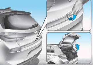
■ 5 Door, Wagon
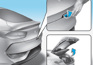
■ Fastback

Copyright © 2025 www.hi30.net