Hyundai i-30: Front Suspension System / Front Stabilizer Bar
Hyundai i30 (PD) 2018-2025 Service Manual / Suspension System (NON-ECS) / Front Suspension System / Front Stabilizer Bar
Repair procedures
| Removal |
| 1. |
Loosen the wheel nuts slightly.
Raise the vehicle, and make sure it is securely supported.
|
| 2. |
Remove the front wheel and tire (A) from the front hub.
|

| 3. |
Disconnect the stabilizer link with the front strut assembly after loosening
the nut (A).
|
| 4. |
Remove the tie rod end ball joint.
|
| 5. |
Loosen the lower arm nut (A) and then remove thelower arm ball joint
by using SST (09568-1S100).
|
| 6. |
Loosen the bolt (A) and then disconnect the universaljoint assembly
from the pinion of the steering gearbox.
|
| 7. |
Remove the roll rod stopper (A) by loosening the boltand nut.
|
| 8. |
Remove the muffler rubber hanger (A).
|
| 9. |
Remove the heat protector (A).
|
| 10. |
Remove the subframe by loosening the mounting bolts and nuts.
|
| 11. |
Loosen the mounting bolts and then remove thestabilizer bar (A).
|
| 12. |
Remove the stabilizer link.
|
| 13. |
Remove the bushing
|
| 14. |
To install, reverse the removal procedure.
|
| 15. |
Check the wheel Alignment.
(Refer to Tires / Wheels - "Alignment")
|
| Inspection |
| 1. |
Check the bushing for wear and deterioration.
|
| 2. |
Check the front stabilizer bar for deformation.
|
| 3. |
Check the front stabilizer link ball joint for damage
|
 Front Lower Arm
Repair procedures
Removal
1.
Loosen the wheel nuts slightly.
Raise the vehicle, and make sure it is securelysupported...
 Sub Frame
Repair procedures
Removal
1.
Loosen the wheel nuts slightly.
Raise the vehicle, and make sure it is securelysupported...
Other information:
Hyundai i30 (PD) 2018-2025 Owner's Manual: Engine compartment
■ Petrol Engine (Kappa 1.0 T-GDI) ■ Petrol Engine (Kappa 1.4 T-GDI) 1. Engine coolant reservoir/Engine coolant cap 2. Brake/clutch fluid reservoir 3. Air cleaner 4. Engine oil dipstick 5. Engine oil filler cap 6. Windscreen washer fluid reservoir 7...
Hyundai i30 (PD) 2018-2025 Service Manual: Air Ventilation Seat
Components and components location Component Location 1. Ventilation seat blower. 2. Ventilation seat unit (Assist seat only). Schematic diagrams Circuit Diagram Air Ventilation Unit Connector No Connecter A Connecter B Connecter C 1 Seat vent unit IGN 1 Driver vent switch led (Low) vent / heater power 2 Driver blower power Driver vent switch led (Mid) Driver heater power 3 Driver blower speed Driver vent switch led (High) Driver heater ground 4 Driver RPM input Driver NTC (+) Driver / Assist, Vent / Heater ground 5 Driver heater switch - vent / heater power 6 Driver vent switch Illumination (-) - 7 Illumination (+) Driver NTC (-) Assist heater power 8 Driver heater LED (Low) Driver blower ground - 9 Driver heater LED (Mid) Driver vent led (Low) Assist heater ground 10 Driver heater LED (High) Driver vent led (Mid) Driver / Assist, Vent / Heater ground 11 Vent seat unit IGN 2 Driver vent led (High) 12 Assist blower power Assist NTC (+) 13 Assist blower speed - 14 Assist blower RPM input - 15 Assist heater switch Assist NTC (-) 16 Assist vent switch Assist blower ground 17 Detent 18 Assist heater LED (Low) 19 Assist heater LED (Mid) 20 Assist heater LED (High) Repair procedures Removal [Ventilation Blower] 1...
Categories
- Manuals Home
- 3rd Generation i30 Owners Manual
- 3rd Generation i30 Service Manual
- Engine coolant
- EPB malfunction indicator
- Shift-lock system. Shift-lock release
- New on site
- Most important about car
Warning light and message
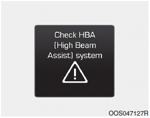
When the High Beam Assist (HBA)
System is not working properly, the
warning message will come on for a
few second. After the message disappears,
the master warning light ( )
will illuminate.
)
will illuminate.

Copyright © 2025 www.hi30.net