Hyundai i-30: ESP (Electronic Stability Program) System / ESP Control Unit
Hyundai i30 (PD) 2018-2025 Service Manual / Brake System / ESP (Electronic Stability Program) System / ESP Control Unit
Components and components location
| Components |
| [LHD] |
| 1. Front - right
tube 2. Rear - left tube 3. Rear - right tube 4. Front - left tube |
5. MC SEC 6. MC PRI 7. ESP Control module (HECU) 8. Bracket |
| [RHD] |
| 1. Front - right
tube 2. Rear - left tube 3. Rear - right tube 4. Front - left tube |
5. MC SEC 6. MC PRI 7. ESP Control module (HECU) 8. Bracket |
Repair procedures
| Removal |
[LHD]
| 1. |
Turn the ignition switch OFF and then disconnect the negative (-) battery
cable.
|
| 2. |
Pull up the lock of the HECU connector (A), then disconnect the connector.
|
| 3. |
Remove the brake fluid from the master cylinder reservoir with a syringe.
|

| 4. |
Disconnect the brake tubes from the HECU by unlocking the nuts counterclockwise
with a spanner.
|
| 5. |
Loosen the HECU bracket bolts (A), then remove HECU and bracket.
|
| 6. |
Remove the 3 bolts, then remove the bracket from HECU.
|
[RHD]
| 1. |
Turn the ignition switch OFF and then disconnect the negative (-) battery
cable.
|
| 2. |
Remove the battery.
(Refer to Engine Electrical System - "Battery")
|
| 3. |
Remove the ECM
(Refer to Engine Control / Fuel System - "Engine Control Module (ECM)")
|
| 4. |
Pull up the lock of the HECU connector and then disconnect the connector.
|
| 5. |
Disconnect the brake tubes from the HECU by unlocking the nuts counterclockwise
with a spanner.
|
| 6. |
Loosen the HECU bracket bolts (A) and then remove HECU and bracket.
|
| 7. |
Remove the 3 bolts, then remove the bracket from HECU.
|
| Installation |
| 1. |
To install, reverse the removal procedure.
|
| 2. |
Tighten the HECU mounting bolts and nuts to the specified torque.
|
| 3. |
After installation, bleed the brake system.
(Refer to ESP(Electronic Stability Program) System - "ESP System Bleeding")
|
| 4. |
Conduct the Variant coding.
|
| 5. |
Conduct the Auto Detected Sensor Calibration.
|
| 6. |
Conduct the Longitudinal G Sensor Calibration.
|
| Adjustment |
Diagnosis procedure by using diagnostic device
As manual for diagnosis methods by using diagnosis device, the main contents
are as follows :
Connect self-diagnosis connector (16pins) located in the lower of driver side
crash pad to self-diagnosis device, and then turn the self-diagnosis device
after key is ON.
Select the "vehicle model" and "ABS/ESC" on diagnostic tool vehicle selection
screen, then select OK.
[Variant Code Reset]
[Auto Detected Sensor Calibration]
[Longitudinal G Sensor Calibration]

 Troubleshooting
Failure Diagnosis
1.
In principle, ESP and TCS controls are prohibited in case of ABS failure.
2...
 ESP OFF Switch
Description and operation
Description
1.
The ESP OFF switch is for the user to turn off the ESP system.
2...
Other information:
Hyundai i30 (PD) 2018-2025 Service Manual: Rear Oil Seal
Repair procedures Removal 1. Remove the dual clutch transmission assembly. (Refer to Double Clutch Transmission (DCT) System - "Double Clutch Transmission (DCT)") 2. Remove the flywheel...
Hyundai i30 (PD) 2018-2025 Service Manual: Rear Bumper Assembly
Components and components location Component Location 1. Rear bumper assembly Repair procedures Replacement • Put on gloves to prevent hand injuries...
Categories
- Manuals Home
- 3rd Generation i30 Owners Manual
- 3rd Generation i30 Service Manual
- Battery replacement
- Front windscreen wiper service position
- Exhaust System (DPF) Warning Light. Glow Indicator Light
- New on site
- Most important about car
Power windows
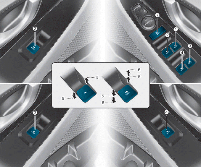
(1) Driver’s door power window
switch
(2) Front passenger’s door power
window switch
(3) Rear door (right) power window
switch
(4) Rear door (left) power window
switch
(5) Window opening and closing
(6) Automatic power window
(7) Power window lock switch

Copyright © 2025 www.hi30.net