Hyundai i-30: Interior Trim / Front Pillar Trim
Components and components location
Repair procedures
| •
|
Put on gloves to prevent hand injuries.
|
|
| •
|
When removing with a flat-tip screwdriver or remover, wrap protective
tape around the tools to prevent damage to components.
|
| •
|
When removing the interior trim pieces, use a plastic panel
removal tool not to damage the surface.
|
| •
|
Take care not to bend or scratch the trim and panels.
|
|
|
1. |
Remove the front pillar trim.
|
(1) |
To remove the front pillar trim, the fastener remover (A) below
must be used.
|
|
(2) |
After slightly lifting up the front pillar trim and putting
the tool in, remove the mounting clip (A) by pulling it.
|
• |
Once the front pillar trim is removed, be sure
to replace the clips with new ones.
|
|
|
|
(3) |
Remove the front pillar trim (A).
|
|
|
2. |
To install, reverse removal procedure.
|
• |
Replace any damaged clips (or pin-type retainers).
|
|
|
Components and components location
Component Location
1. Cowl side
trim
Repair procedures
Replacement
•
Put on gloves to prevent hand injuries...
Components and components location
Component Location
1. Center pillar
lower trim
2. Center pillar
upper trim
Repair procedures
Replacement
[Center pillar lower trim]
•
Put on gloves to prevent hand injuries...
Other information:
Description and operation
Description
Camshaft Position Sensor (CMPS) is a hall sensor and detects the camshaft position
by using a hall element.
It is related with Crankshaft Position Sensor (CKPS) and detects the piston
position of each cylinder which the CKPS can't detect...
Specifications
Description
Specification
Limit
General
Type
In-line, DOHC
Number of cylinders
4
Bore
71...
Categories
If your vehicle is equipped with a
sunroof, you can slide or tilt your
sunroof with the sunroof control lever
located on the overhead console.
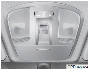
The ignition switch must be in the ON
position before you can open or
close the sunroof.
The sunroof can be operated for
approximately 30 seconds after the
ignition key is removed or turned to
the ACC or LOCK(or OFF) position.
However, if the front door is opened,
the sunroof cannot be operated even
within 30 seconds.
read more


 Cowl Side Trim
 Center Pillar Trim