Hyundai i-30: Indicators And Gauges / Instrument Cluster
Hyundai i30 (PD) 2018-2025 Service Manual / Body Electrical System / Indicators And Gauges / Instrument Cluster
Components and components location
| Components |
TFT LCD Cluster (Standard)
TFT LCD Cluster (7Inch)
Connector Pin Information

Connector Pin Information
|
No. |
Description |
No. |
Description |
|
1 |
Ground |
21 |
Trip switch (-) |
|
2 |
Illumination (-) |
22 |
Trip switch 1 (+) |
|
3 |
Rheostat switch (Down)_Input |
23 |
Trip switch 2 (+) |
|
4 |
Rheostat switch (Up)_Input |
24 |
M/T N switch |
|
5 |
Dentent |
25 |
Driver mode switch |
|
6 |
P |
26 |
- |
|
7 |
R |
27 |
- |
|
8 |
N |
28 |
Low washer level sensor |
|
9 |
D |
29 |
M-CAN (Low) |
|
10 |
S |
30 |
M-CAN (High) |
|
11 |
Immobillizer |
31 |
- |
|
12 |
Vehicle speed_Output |
32 |
C-CAN (High) |
|
13 |
Alternator_Input |
33 |
C-CAN(Low) |
|
14 |
Fuel sender (+)_Input |
34 |
- |
|
15 |
- |
35 |
- |
|
16 |
Fuel sender (-)_Input |
36 |
- |
|
17 |
Water separator (+) |
37 |
Ground |
|
18 |
Airbag (+)_Input |
38 |
- |
|
19 |
Oil press switch (-)_Input |
39 |
IGN 1 |
|
20 |
Tail_input |
40 |
Battery (+) |
Schematic diagrams
| Circuit Diagram |
TFT LCD Cluster (Standard)
TFT LCD Cluster (7Inch)
Description and operation
| Description |
Communication Network Diagram
|
Abbreviation |
Expalnation |
|
ECM |
Engine Control Module |
|
TCU |
Transmission Control Unit |
|
MDPS |
Motor Driven Power Steering |
|
AEB |
Autonomous Emergency Braking |
|
LKAS |
Lane Keeping Assist System |
|
FPS |
Fuel Pump Control module |
|
RR CAMERA |
Rear View Carmera |
|
VACUUM |
Vacuum Pump |
|
CLUSTER |
Cluster Module |
|
ACU |
Airbag Control Unit |
|
DATC |
Dual Automatic Temp Control |
|
MTC |
Temp Control |
|
OCS |
Occupant Classification System |
|
VDC |
Vehicle Dynamic Control |
|
BSD |
Blind Spot Detection |
|
AMP |
Amplifier |
|
AVN |
Head Unit (Audio / AVN) |
|
SMK |
Smart Key Unit |
|
WPC |
Wireless Power Charger |
|
IMS |
Integrated Memory System |
|
DDM |
Driver Door Module |
|
ADM |
Assist Door Module |
|
BCM |
Body Control Module |
|
B-CAN |
Body Controller Area Network |
|
P-CAN |
Powertrain Controller Area Network |
|
M-CAN |
Multi media Controller Area Network |
|
C-CAN |
Chassis Controller Area Network |
Cluster Variant Coding
As we have more options (ESC, MDPS etc.) in the car, the dashboard now has more
information to display depending on the chosen options.
For this reason, we need to learn which options the vehicle has when replacing
the dashboard.
To address this issue, a course of learning based on the option required for
the vehicle when replacing the dashboard should be carried out.
This is called Variant Coding.
Function
| 1. |
High speed CAN communication (C-CAN)
|
| 2. |
Low speed CAN communication (M-CAN)
|
| 3. |
Sound output
Various alarms and sound effects are issued through the external speakers
connected to the dashboard.
|
| 4. |
User Setting Mode (USM)
Setting can be changed by using switchs (Menu, UP, Down and OK button).
There are many items (for example, In/Out Seat Synchronization, In/Out
Steering Wheel Synchronization, Auto Door Lock, Auto Door Lock Deactivate,
Head Lamp Escort, Welcome Light, Welcome Sound, One Touch Turn Signal,
Average Fuel Consumption Auto Reset, Brightness, and Content Setup)
that can be set and customized. The signal flow during setting is as
follows.
|

Repair procedures
| Removal |
|

Instrument Cluster
| 1. |
Disconnect the negative (-) battery terminal.
|
| 2. |
Remove the cluster fascia panel.
(Refer to Body - "Cluster Fascia Panel")
|
| 3. |
Separate the instrument cluster (A) after loosening the mounting screws.
|
| 4. |
Remover the instrument cluster after disconnecting the cluster connector
(A).
|
| Installation |
Instrument Cluster
| 1. |
Install the cluster after connect the cluster connectors.
|
| 2. |
Install the cluster fascia panel.
|
| 3. |
Connect the negative (-) battery terminal.
|
Instrument Cluster Speaker
| 1. |
Install the cluster speaker after connect the cluster connectors.
|
| 2. |
Install the cluster facia upper panel.
|
| 3. |
Connect the negative (-) battery terminal.
|
| Inspection |
| 1. |
Check point (Warning indicator)
|


| 2. |
Check point (Gauge)
|
Diagnosis with Diagnostic tool
| 1. |
In the body electrical system, failure can be quickly diagnosed by using
the vehicle diagnostic system (Diagnostic tool).
The diagnostic system (Diagnostic tool) provides the following information.
|
| 2. |
If diagnose the vehicle by Diagnostic tool, select "DTC Analysis" and
"Vehicle".
|
| 3. |
If check current status, select the "Data Analysis" and "Car model".
|
| 4. |
Select the 'CLU' to search the current state of the input/output data.
|
CLU Variant Coding
As we have more options (ESC, TPMS, SCC, etc.) in the car, the dashboard now
have more information to display depending on the chosen options.
For this reason, we need to learn which options the current vehicle when we
replace the dashboard.
To address this issue, a course of learning based on the option required for
the vehicle when replacing the dashboard should be carried out.
This is called Variant Coding.
| 1. |
Connect the cable of Diagnostic tool to the data link connector in driver
side crash pad lower panel.
|
| 2. |
Select the 'S/W Management' and 'Car model'.
|
| 3. |
Select the 'Cluster Module' and 'CLU Variant Coding'.
|
 Troubleshooting
Troubleshooting
Error Item
Failure symptom
Inspection items
Detailed inspections
Relevant Parts/
Components
Screen display
TFT-LCD screen does not turn on
1)
Connector attachments
2)
Components
1)
Check the connector attachments
2)
Check B+, IGN and GND wiring
3)
Check the components
Connectors, wiring, fuses, dashboard
Warning light
Airbag warning lamp malfunction
1)
Connector attachments
2)
C-CAN
3)
Components
1)
Check airbag + signal (connectors)
2)
Check C-CAN (ACU4) signal
3)
Check the FPC attachment inside the dashboard
ACU Connectors, wiring, fuses, dashboard
Mode conversion
Integrated driving mode malfunction
1)
Connector attachments
2)
Switch
3)
Components
1)
Check the switch input (connector)
2)
Check the switch signal input
(disconnection or shorting)
3)
Check conversion with dashboard component
Switch connector, wiring dashboard
Illumination
Interior light brightness cannot be controlled...

Other information:
Hyundai i30 (PD) 2018-2025 Service Manual: Fuel pressure test
Fuel Pressure Test 1. Release the residual pressure in fuel line. (Refer to Fuel Delivery System - "Release Residual Pressure in Fuel Line") • When removing the fuel pump relay, the diagnostic trouble code (DTC) will be occurred...
Hyundai i30 (PD) 2018-2025 Service Manual: Components and components location
Component Location 1. Smart key unit (SMK) 2. Body control module (BCM) 3. Interior antenna 1 4. Interior antenna 2 5. FOB key 6. Start Stop Button (SSB) 7. Door handle & door antenna 8...
Categories
- Manuals Home
- 3rd Generation i30 Owners Manual
- 3rd Generation i30 Service Manual
- Cruise control
- Theft-alarm system
- Brake/clutch fluid
- New on site
- Most important about car
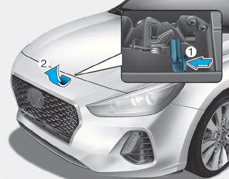
Bonnet
Opening the bonnet
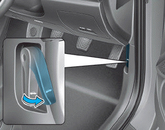
1. Park the vehicle and set the parking brake.
2. Pull the release lever to unlatch the bonnet. The bonnet should pop open slightly.

Copyright © 2025 www.hi30.net