Hyundai i-30: Front Suspension System / Front Stabilizer Bar
Hyundai i30 (PD) 2018-2025 Service Manual / Suspension System (NON-ECS) / Front Suspension System / Front Stabilizer Bar
Repair procedures
| Removal |
| 1. |
Loosen the wheel nuts slightly.
Raise the vehicle, and make sure it is securely supported.
|
| 2. |
Remove the front wheel and tire (A) from the front hub.
|

| 3. |
Disconnect the stabilizer link with the front strut assembly after loosening
the nut (A).
|

| 4. |
Remove the tie rod end ball joint.
|
| 5. |
Loosen the lower arm nut (A) and then remove the lower arm ball joint
by using SST(09568-1S100).
|
| 6. |
Loosen the bolt (A) and then disconnect the universal joint assembly
from the pinion of the steering gear box.
|
| 7. |
Remove the roll rod stopper (A) by loosening the bolt and nut.
|
| 8. |
Remove the muffler rubber hanger (A).
|
| 9. |
Remove the heat protector (A).
|
| 10. |
Remove the subframe by loosening the mounting bolts and nuts.
|
| 11. |
Loosen the mounting bolts and then remove the stabilizer bar (A).
|
| 12. |
Remove the stabilizer link.
|
| 13. |
Remove the bushing
|
| 14. |
To install, reverse the removal procedure.
|
| 15. |
Check the wheel Alignment.
(Refer to Tires / Wheels - "Alignment")
|
| Inspection |
| 1. |
Check the bushing for wear and deterioration.
|
| 2. |
Check the front stabilizer bar for deformation.
|
| 3. |
Check the front stabilizer link ball joint for damage
|
 Front Lower Arm
Repair procedures
Removal
1.
Loosen the wheel nuts slightly.
Raise the vehicle, and make sure it is securely supported...
 Sub Frame
Repair procedures
Removal
1.
Loosen the wheel nuts slightly.
Raise the vehicle, and make sure it is securely supported...
Other information:
Hyundai i30 (PD) 2018-2025 Service Manual: Description and operation
Description The immobilizer system will disable the vehicle unless the proper ignition key is used, in addition to the currently available anti-theft systems such as car alarms, the immobilizer system aims to drastically reduce the rate of auto theft...
Hyundai i30 (PD) 2018-2025 Owner's Manual: Front seats
The front seat can be adjusted by using the control lever (or knob) or switches located on the outside of the seat cushion. Before driving, adjust the seat to the proper position so that you can easily control the steering wheel, foot pedals and controls on the instrument panel...
Categories
- Manuals Home
- 3rd Generation i30 Owners Manual
- 3rd Generation i30 Service Manual
- Recommended lubricants and capacities
- EPB malfunction indicator
- Front windscreen wiper service position
- New on site
- Most important about car
Power windows
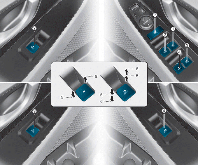
(1) Driver’s door power window
switch
(2) Front passenger’s door power
window switch
(3) Rear door (right) power window
switch
(4) Rear door (left) power window
switch
(5) Window opening and closing
(6) Automatic power window
(7) Power window lock switch

Copyright © 2025 www.hi30.net