Hyundai i-30: Front Suspension System / Sub Frame
Repair procedures
| Removal |
| 1. |
Loosen the wheel nuts slightly.
Raise the vehicle, and make sure it is securely supported.
|
| 2. |
Remove the front wheel and tire (A) from the front hub.
|

| 3. |
Disconnect the stabilizer link with the front strut assembly after loosening
the nut (A).
|
| 4. |
Remove the tie rod end ball joint.
|
| 5. |
Loosen the lower arm nut (A) and then remove the lower arm ball joint
by using SST(09568-1S100).
|
| 6. |
Loosen the bolt (A) and then disconnect the universal joint assembly
from the pinion of the steering gear box.
|
| 7. |
Remove the roll rod stopper (A) by loosening the bolt and nut.
|
| 8. |
Remove the muffler rubber hanger (A).
|
| 9. |
Remove the heat protector (A).
|
| 10. |
Remove the subframe by loosening the mounting bolts and nuts.
|
| 11. |
Loosen the mounting bolts and then remove the stabilizer bar (A).
|
| 12. |
Remove the protector (A), (B) and (C).
|
| 13. |
Remove the steering gearbox (A) by loosening the mounting bolts.
|
| 14. |
Remove the front lower arm after loosening the bolts & nuts.
|
| 15. |
To install, reverse the removal procedure.
|
| 16. |
Check the front alignment.
(Refer to Suspension System - "Front Alignment")
|
 Front Stabilizer Bar
Repair procedures
Removal
1.
Loosen the wheel nuts slightly.
Raise the vehicle, and make sure it is securely supported...

Other information:
Hyundai i30 (PD) 2018-2025 Service Manual: Components and components location
..
Hyundai i30 (PD) 2018-2025 Owner's Manual: The battery sensor deactivation
The battery sensor is deactivated, when the battery is disconnected from the negative pole for maintenance purpose. In this case, the ISG system is limitedly operated due to the battery sensor deactivation. Thus, the driver needs to take the following procedures to reactivate the battery sensor after disconnecting the battery...
Categories
- Manuals Home
- 3rd Generation i30 Owners Manual
- 3rd Generation i30 Service Manual
- Recommended lubricants and capacities
- Drive mode integrated control system
- Shift-lock system. Shift-lock release
- New on site
- Most important about car
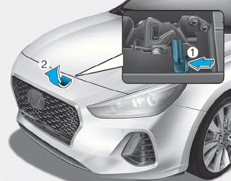
Bonnet
Opening the bonnet
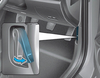
1. Park the vehicle and set the parking brake.
2. Pull the release lever to unlatch the bonnet. The bonnet should pop open slightly.

Copyright © 2025 www.hi30.net