Hyundai i-30: Power Door Mirrors / Power Door Mirror Switch
Hyundai i30 (PD) 2018-2025 Service Manual / Body Electrical System / Power Door Mirrors / Power Door Mirror Switch
Components and components location
| Components |
Schematic diagrams
| Circuit Diagram |
Repair procedures
| Inspection |
Power Window Switch
| 1. |
Disconnect the negative (-) battery terminal.
|
| 2. |
Remove the driver door trim.
(Refer to Body - "Front Door Trim")
|
| 3. |
Disconnect the power mirror switch connector from the door trim.
|
| 4. |
Check for continuity between the terminals in each switch position as
shown below.
[Power Mirror Switch]
[Power Folding Mirror Switch]
|
| Removal |
Driver Power Window Switch
| 1. |
Disconnect the negative (-) battery terminal.
|
| 2. |
Remove the front driver door trim.
(Refer to Body - "Front Door Trim")
|
| 3. |
Remove the power window switch assembly (A).
|
| Installation |
| 1. |
Install the power window switch assembly.
|
| 2. |
Install the amrest from the door trim.
|
| 3. |
Install the front door trim.
|
| 4. |
Connect the negative (-) battery terminal.
|

 Power Door Mirror Actuator
Components and components location
Components
1. BSD Indicator
2. Side repeater
lamp
Repair procedures
Inspection
1...
Other information:
Hyundai i30 (PD) 2018-2025 Service Manual: Description and operation
Description The ECM (Electro Chromatic inside rear view Mirror) is one that automatically dims to protect the driver’s eyes when it senses light reflecting from the car behind. The sensor in the mirror detects the brightness and if the headlight from the car behind is reflected on the mirror, the chemical layer inside the mirror reacts to glare and adjusts the reflectivity from 10 to 70%...
Hyundai i30 (PD) 2018-2025 Owner's Manual: Battery replacement
If the Smart Key is not working properly, try replacing the battery with a new one. Battery Type: CR2032 To replace the battery: 1. Remove the mechanical key. 2. Use a slim tool to pry open the rear cover of the smart key. 3. Remove the old battery and insert the new battery...
Categories
- Manuals Home
- 3rd Generation i30 Owners Manual
- 3rd Generation i30 Service Manual
- Light bulbs
- Engine compartment
- FCA sensor
- New on site
- Most important about car
Tailgate
Opening the tailgate
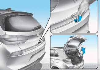
■ 5 Door, Wagon
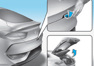
■ Fastback

Copyright © 2025 www.hi30.net