Hyundai i-30: Motor Driven Power Steering / Steering Gear Box
Hyundai i30 (PD) 2018-2025 Service Manual / Steering System / Motor Driven Power Steering / Steering Gear Box
Repair procedures
| Removal |
| 1. |
Loosen the wheel nuts slightly.
Raise the vehicle, and make sure it is securely supported.
|
| 2. |
Remove the front wheel and tire (A) from the front hub.
|

| 3. |
Disconnect the stabilizer link from the front strut assembly after loosening
the nut (A).
|
| 4. |
Remove the tie rod end ball joint.
|
| 5. |
Loosen the lower arm nut (A) and then remove the lower arm ball joint
by using SST (09568-1S100).
|
| 6. |
Loosen the bolt (A) and then disconnect the universal joint assembly
from the pinion of the steering gear box.
|
| 7. |
Remove the roll rod stopper (A) by loosening the bolt and nut.
|
| 8. |
Remove the muffler rubber hanger (A).
|
| 9. |
Remove the heat protector (A).
|
| 10. |
Remove the subframe by loosening the mounting bolts and nuts.
|
| 11. |
Remove the protector (A), (B) and (C).
[RHD]
[LHD]
|
| 12. |
Remove the steering gearbox (A) by loosening the mounting bolts.
[LHD]
[RHD]
|
| 13. |
To install, reverse the removal procedure.
|
| 14. |
Check the front alignment.
(Refer to Suspension System - "Front Alignment")
|
| Replacement |
|
| Tie rod end |
| 1. |
Remove the tie rod end after loosening the nut.
|
| 2. |
Replace with new parts.
|
| 3. |
Check the alignment.
(Refer to Tires/ Wheels - "Alignment")
|
 MDPS Assembly
Repair procedures
Removal
1.
Disconnect the battery negative cable from the battery and then wait
for at least 30 seconds...
 Restraint
..
Other information:
Hyundai i30 (PD) 2018-2025 Owner's Manual: Checking the engine oil level (Diesel engine)
1. Be sure the vehicle is on level ground. 2. Start the engine and allow it to reach normal operating temperature. 3. Turn the engine off and wait for a few minutes (about 5 minutes) for the oil to return to the oil pan. 4. Pull the dipstick out, wipe it clean, and re-insert it fully...
Hyundai i30 (PD) 2018-2025 Service Manual: Lift and Support Points
Lift and Support Points • When heavy rear components such as suspension, fuel tank, spare tire, tailgate and trunk lid are to be removed, place additional weight in the luggage area before hoisting...
Categories
- Manuals Home
- 3rd Generation i30 Owners Manual
- 3rd Generation i30 Service Manual
- Light bulbs
- Brake/clutch fluid
- LKA system operation
- New on site
- Most important about car
Power windows
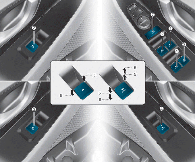
(1) Driver’s door power window
switch
(2) Front passenger’s door power
window switch
(3) Rear door (right) power window
switch
(4) Rear door (left) power window
switch
(5) Window opening and closing
(6) Automatic power window
(7) Power window lock switch

Copyright © 2025 www.hi30.net