Hyundai i-30: Intake and Exhaust System / Turbo Charger & Exhaust Manifold
Hyundai i30 (PD) 2018-2025 Service Manual / Engine Mechanical System / Intake and Exhaust System / Turbo Charger & Exhaust Manifold
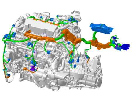
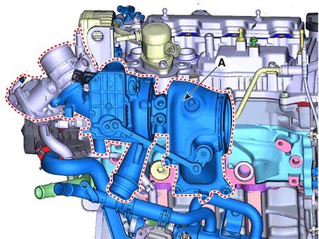
Components and components location
| Components |
| 1. Catalytic
converter (WCC) 2. Turbo manifold module 3. Catalytic converter (WCC) heat protector 4. Turbo charger gasket 5. Catalytic converter (WCC) gasket 6. V - clamp 7. Oxygen sensor 8. Catalytic converter (WCC) upper stay |
9. Catalytic
converter (WCC) stay 10. Turbo charger oil feed pipe gasket 11. Turbo charger oil feed pipe 12. Turbo charger water feed pipe 13. Turbo charger oil drain pipe 14. Turbo charger oil drain B gasket 15. Turbo charger oil drain A gasket 16. Turbo charger water drain pipe |
Repair procedures
| Removal and Installation |
| 1. |
Disconnect the battery negative teminal.
|
| 2. |
Remove the engine cover.
(Refer to Engine and Transaxle Assembly - "Engine Cover")
|
| 3. |
Remove the air duct and air cleaner assembly.
(Refer to Intake and Exhaust System - "Air Cleaner")
|
| 4. |
Remove the intercooler inlet hose and pipe.
|

| 5. |
Disconnect the wiring connectors and harness clamps and remove the wiring
protector around the exhaust manifold.
|
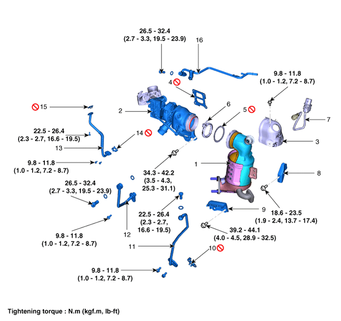
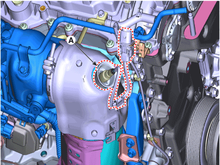
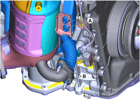
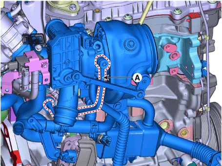
| 6. |
Remove the oxygen sensor (A).
|
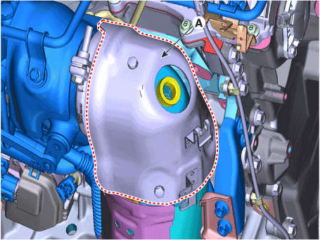
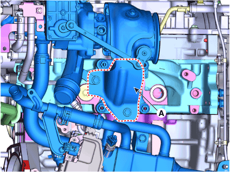
| 7. |
Remove the heat protector (A).
|
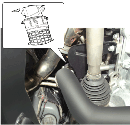
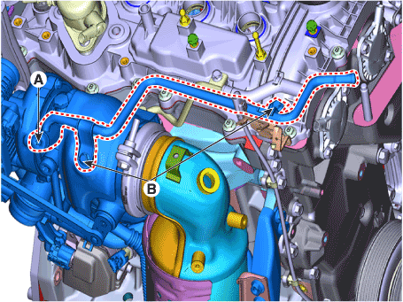
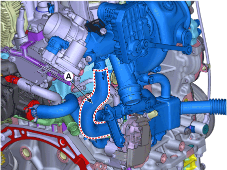
| 8. |
Remove the turbocharger water drain pipe (A) and the wiring connector
bracket (B).
|
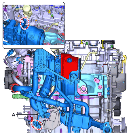
| 9. |
Remove the catalytic converter (WCC) bracket (A) and EGR pipe A (B).
|
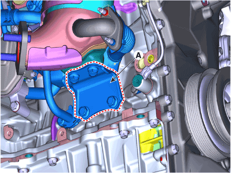
| 10. |
Remove the catalytic converter (WCC) stay (A).
|
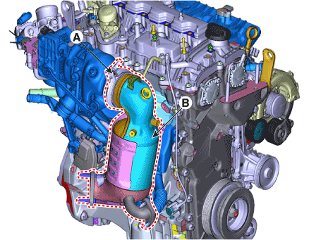
| 11. |
Remove the V-clamp (A) and then remove the catalytic converter (WCC)
(B) with the gasket.
|
| 12. |
Remove the turbo charger oil feed pipe (A).
|
| 13. |
Remove the turbo charger water feed pipe (A).
|
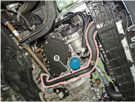
| 14. |
Remove the turbo charger lower heat protector (A).
|
| 15. |
Remove the turbo charger oil drain pipe (A).
|
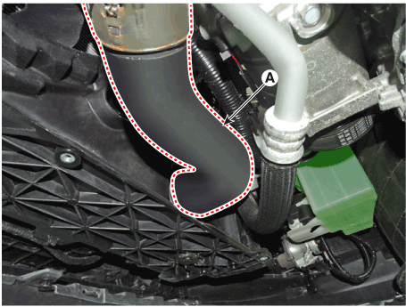
| 16. |
Discoccect the EGR cooler hose (A).
|
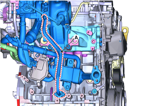
| 17. |
Remove the turbo manifold module (A) with the gasket.
|
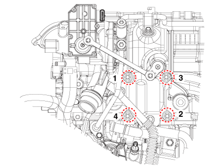
| 18. |
Install in the reverse order of removal.
|
 Turbo Charger
Components and components location
Comoinents
1. Heat protector
2. DPV assy
3. Turbine housing
4. Compressor housing
5...
 Muffler
Components and components location
Components
1. Front muffler
2. GPF
3. Center muffler
4. Rear muffler
5...
Other information:
Hyundai i30 (PD) 2018-2025 Service Manual: Front Door Inside Handle
Repair procedures Replacement 1. Remove the front door trim. (Refer to Front Door - "Front Door Trim") 2. After loosening the mounting screws, remove the front door inside handle (A)...
Hyundai i30 (PD) 2018-2025 Service Manual: Components and components location
..
Categories
- Manuals Home
- 3rd Generation i30 Owners Manual
- 3rd Generation i30 Service Manual
- Brake/clutch fluid
- Front windscreen wiper service position
- Recommended lubricants and capacities
- New on site
- Most important about car
Air bag - supplemental restraint system
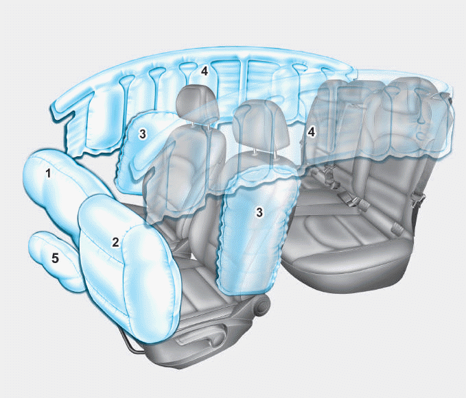
1. Driver’s front air bag
2. Passenger’s front air bag
3. Side air bag*
4. Curtain air bag*
5. Knee air bag*
6. Front passenger air bag ON/OFF
switch

Copyright © 2025 www.hi30.net