Hyundai i-30: Dual Clutch Transmission Control System / Clutch Actuator & TCM Assembly
Specifications
Item
|
Specification
|
Rated voltage
|
12V
|
Rod length
|
79.0 - 80.0 mm (3.1102 - 3.1496 in.)
|
Wear adjustment amount
|
0.25 mm (0.0098 in.) @ 1 Click
|
Components and components location
1. Fork cover
2. Clutch actuator & TCM assembly
3. Clutch actuator assembly
|
4. O-ring
5. DCT control module (TCM)
|
Repair procedures
|
1. |
The DCT system can be more quickly diagnosed for troubles by using the
vehicle diagnostic system (diagnostic tool). (Refer to DTC guide)
diagnostic tool provides the following information.
| 1) |
Self diagnosis : Inspects and displays diagnostic trouble code
(DTC)
|
| 2) |
Sensor data : Checks the system input/output value status
|
| 3) |
Forced operation : Checks the system operating status
|
| 4) |
Additional function : Controls system options, zero point adjustment
and other functions
|
|
|
1. |
Turn ignition switch OFF and disconnect the battery negative (-) terminal.
|
|
2. |
Remove the air cleaner assembly.
(Refer to Engine Mechanical System - "Air cleaner")
|
|
3. |
Disconnecting the TCM connector (A).
|
|
4. |
Loosen the ground mounting bolt (A)
|
Tightening torque :
9.8 - 11.8 N.m (1.0 - 1.2 kgf.m, 7.2 - 8.7 lb-ft)
|
|
|
5. |
Loosen the clutch actuator upper mounting bolts (A).
|
Tightening torque :
19.6 - 26.5 N.m (2.0 - 2.7kgf.m, 14.5 - 19.5 lb-ft)
|
|
|
6. |
Remove the engine room under cover.
(Refer to Engine Mechanical System - "Engine Room Under Cover")
|
|
7. |
Loosen the ground and bracket mounting bolt (A).
|
Tightening torque :
9.8 - 11.8 N.m (1.0 - 1.2 kgf.m, 7.2 - 8.7 lb-ft)
|
|
|
8. |
Remove the fork cover (A).
|
Tightening torque :
3.9 - 5.9 N.m (0.4 - 0.6 kgf.m, 2.9 - 4.3 lb-ft)
|
|
|
9. |
Loosen the starter mounting bolt (A).
|
Tightening torque :
49.0 - 63.7 N.m (5.0 - 6.5 kgf.m, 36.2 - 47.0 lb-ft)
|
|
|
10. |
Loosen the transmission lower mounting bolt (A).
|
Tightening torque :
42.2 - 53.9 N.m (4.3 - 5.5 kgf.m, 31.1 - 39.8 lb-ft)
|
|
|
11. |
Fix the clutch engagement fork after installing special service tool
(0K430-Q5100).
|
|
12. |
Remove the clutch actuator & TCM assembly (A) after loosening the lower
mounting bolts.
|
Tightening torque :
19.6 - 26.5 N.m (2.0 - 2.7kgf.m, 14.5 - 19.5 lb-ft)
|
|
|
1. |
To install, reverse the removal procedures.
|
|
2. |
Check the assembled state of the dowel pins (A) before installing the
clutch actuator assembly.
|
|
3. |
Perform the clutch touch point learning procedure using the diagnostic
tool.
|
• |
Even if you removed and reinstalled the clutch actuator,
be sure to perform the touch point learning.
|
|
• |
If you have replaced the dual clutch assembly or clutch
actuator, be sure to perform the touch point learning.
|
|
|
| •
|
If you replaced the dual clutch assembly or clutch actuator,
be sure to perform wear compensation by referring to the following
table.
Case
|
Replaced Part
|
Wear Compensation (Clutch Actuator)
|
A
|
Clutch actuator only
|
Rewind the rod to adjust rod length
|
B
|
Dual Clutch assembly only
|
Initialize the rod length
|
C
|
Both dual clutch assembly and clutch actuator
|
Do not adjust the rod length
|
|
|
A. Rewinding the rod to adjust rod length (when only the clutch actuator is
replaced)
| •
|
Be sure to perform it when you have replaced the clutch actuator
but reuse the dual clutch assembly.
|
| •
|
It is performed to adjust the rod length of a new clutch actuator
to that of an old clutch actuator.
|
|
|
1. |
Remove the clutch actuator assembly.
(Refer to Clutch Actuator Assembly - "Removal")
|
|
2. |
Slightly pull the lever of the clutch actuator removed from the vehicle
and measure the length of each old rod (C).
|
Length of the old rod (C) : Length from the reference plane
(A) to the end of the rod (B).
|
| 2) |
Clutch actuator 2
|
|
• |
If the rod length is less than 52 mm (2.0472 in.), replace
all of the dual clutch assembly, clutch actuator, and
engagement bearing.
|
|
|
|
3. |
Remove sealing rubber (A) of new part clutch actuator.
|
|
4. |
Press the end part of rod (A) and release the pressing force when you
see the nut bump (B).
|
• |
Light inside of the hole (C) and check the nut bump
(B) inside of it.
|
|
• |
Repeat the operation if the nut bump (B) does not come
down to the assembly hole position.
|
|
• |
The nut bump (B) can be moved up a little by sealing
boot if the pressing force is released.
|
|
|
|
5. |
Insert a special tool (0K430-Q5300) (A) to a sealing rubber hole.
Rotate the SST clockwise and adjust the length of the new clutch actuator's
rod to the "length of old rod", which was measured at step No. 2.
|
Increasing (+) rod length : Rotate counter-clockwise / once
+0.25mm (+0.0098 in.)
Shortening (-) rod length : Rotate clockwise / once -0.25mm
(-0.0098 in.)
|
|
• |
Perform the same procedure for the opposite side rod.
|
|
|
• |
Be aware not to break the clutch actuator caused by
break away inner parts when the SST over rotates clockwise.
|
|
• |
If the "length of the clutch actuator's new rod" is
not adjusted to the "length of the old rod" measured
at step No. 2, the DCT shift shock may occur or driving
may be impossible.
|
|
|
|
6. |
Slightly pull the lever of the clutch actuator and check whether the
"length of the rod which the final adjustment is finished" is same with
the "length of the old rod" measured at step No. 2.
|
Rod length (C) : Length from the reference plane (A) to the
end of the rod (B).
|
|
|
7. |
Install the sealing rubber (A).
|
B. Initializing the rod length (When only the dual clutch assembly is replaced
or Both dual clutch assembly and clutch actuator is replaced)
| •
|
Be sure to perform it when you have replaced the dual clutch
assembly but reuse the clutch actuator.
|
| •
|
Perform the procedure when both the dual clutch assembly and
clutch actuator are replaced.
|
| •
|
It is performed to adjust the rod length of an old clutch actuator
to that of a new clutch actuator.
|
|
|
1. |
Remove the clutch actuator assembly.
(Refer to Clutch Actuator Assembly - "Removal")
|
|
2. |
Remove sealing rubber (A) from old part clutch actuator.
|
|
3. |
Slightly pull the lever of the clutch actuator removed from the vehicle
and measure length of each rod (C). If the length is shorter than the
initialization length, you need to perform initialization.
|
Rod length (C) : Length from the reference plane (A) to the
end of the rod (B).
(Initializ rod length : 79.0 - 80.0 mm (3.1102 - 3.1496 in.)
|
| 2) |
Clutch actuator 2
|
|
|
4. |
Press the end part of rod (A) and release the pressing force when you
see the nut bump (B).
|
• |
Light inside of the hole (C) and check the nut bump
(B) inside of it.
|
|
• |
Repeat the operation if the nut bump (B) does not come
down to the assembly hole position.
|
|
• |
The nut bump (B) can be moved up a little by sealing
boot if the pressing force is released.
|
|
|
|
5. |
Insert a special tool (0K430-Q5300) (A) to a sealing rubber hole.
Rotate the SST counter-clockwise and adjust the length of the clutch
actuator's rod.
|
Increasing (+) rod length : Rotate counter-clockwise / once
+0.25mm (+0.0098 in.)
Shortening (-) rod length : Rotate clockwise / once -0.25mm
(-0.0098 in.)
|
|
• |
Perform the same procedure for the opposite side rod.
|
|
|
• |
Be aware not to break the clutch actuator caused by
break away inner parts when the SST over rotates clockwise.
|
|
• |
If the rod length is not initialized to 79.0 - 80.0
mm (3.1102 - 3.1496 in.) during initialization of wear
compensation, DCT shift shock may occur or driving may
be impossible.
|
|
|
|
6. |
Slightly pull the lever of the clutch actuator and check whether the
"length of the rod which the final adjustment is finished" is same with
the "rod's initialized length".
|
Rod length (C) : Length from the reference plane (A) to the
end of the rod (B).
(Initializ rod length : 79.0 - 80.0 mm (3.1102 - 3.1496 in.)
|
| 2) |
Clutch actuator 2
|
|
|
7. |
Install the sealing rubber (A).
|
|
8. |
Remove the clutch actuator assembly from the special tool (0K430-Q5300).
|
Description and operation
Description
•
Function
The Transmission Control Module (TCM) is like the brain for the Dual
Clutch Transmission (DCT)...
Specifications
Specification
Item
Specification
Operation condition
-40 to 257 °F (- 40 to 125 °C )
Rated voltage
12V
Description and operation
Description
•
Gear actuator uses signals from TCM to control the gear...
Other information:
Components and components location
Components location (1)
Heated steering wheel switch
1. Heated steering switch
Heated steering wheel control module
(Body control moduel(BCM))
1...
Repair procedures
Removal
1.
Disconnect the negative (-) battery terminal.
2.
Remove the luggage lamp by using the (-) screw driver.
•
Be careful not to damage the luggage trim...
Categories
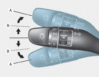
To signal a turn, push down on the
lever for a left turn or up for a right
turn in position (A). To signal a lane
change, move the turn signal lever
slightly and hold it in position (B).The
lever will return to the OFF position
when released or when the turn is
completed.
read more


 DCT Control Module (TCM)
 Gear Actuator Assembly