Hyundai i-30: Dual Clutch Transmission Control System / Gear Actuator Assembly
Hyundai i30 (PD) 2018-2025 Service Manual / DCT(Dual Clutch Transmission) System / Dual Clutch Transmission Control System / Gear Actuator Assembly
Specifications
| Specification |
|
Item |
Specification |
|
Operation condition |
-40 to 257 °F (- 40 to 125 °C ) |
|
Rated voltage |
12V |
Description and operation
| Description |
| • |
Gear actuator uses signals from TCM to control the gear.
|
Components and components location
| Components |
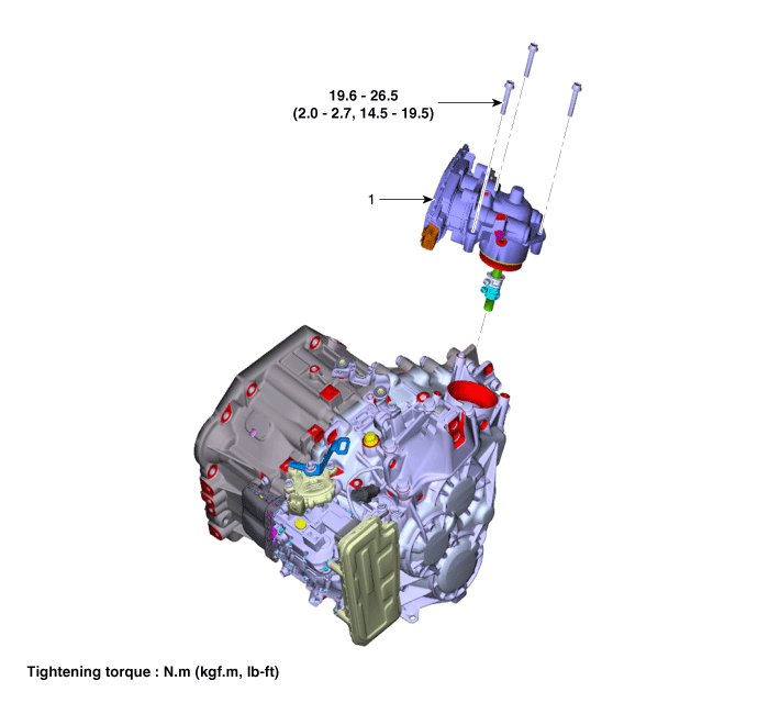
| 1. Gear actuator
assembly |
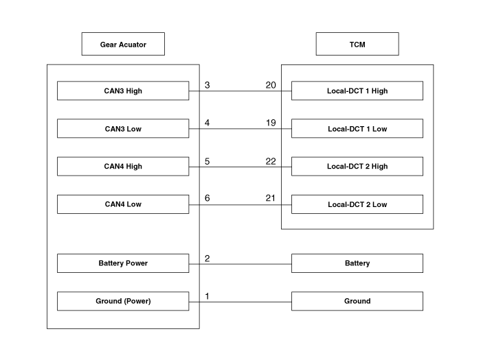
Schematic diagrams
| [Connector and Terminal Function] |
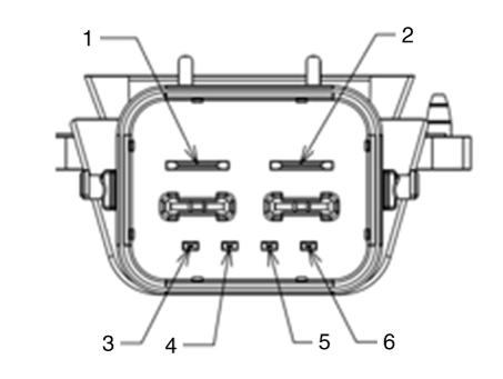
|
Pin |
Description |
Pin |
Description |
|
1 |
Ground (Power) |
4 |
CAN3 Low |
|
2 |
Battery Power |
5 |
CAN4 High |
|
3 |
CAN3 High |
6 |
CAN4 Low |
| [Circuit Diagram] |
Repair procedures
| Inspection |
| 1. |
The DCT system can be more quickly diagnosed for troubles by using the
vehicle diagnostic system (diagnostic tool). (Refer to DTC guide)
diagnostic tool provides the following information.
|
| Removal |
| 1. |
Turn ignition switch OFF and disconnect the battery negative (-) terminal.
|
| 2. |
Remove the air cleaner assembly and air duct.
(Refer to Engine Mechnical System - "Air Cleaner")
|
| 3. |
Remove the battery and battery tray.
(Refer to Engine Electrical System - "Battery")
|
| 4. |
Remove the ECM.
(Refer to Engine Control System - "ECM")
|
| 5. |
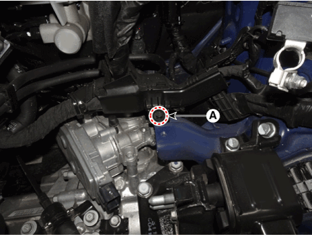
Disconnect the gear actuator connector (A).
|
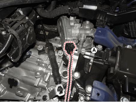
| 6. |
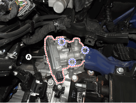
Loosen the wiring mounting bolt (A).
|
| 7. |
Remove the gear actuator assembly after loosening bolts (A).
|
| Installation |
| 1. |
To install, reverse the removal procedure.
|

 Clutch Actuator & TCM Assembly
Specifications
Specification
Item
Specification
Rated voltage
12V
Rod length
79...
 Input Speed Sensor
Specifications
Specification
Item
Specification
Type
Hall effect sensor
Output signal
High: 11...
Other information:
Hyundai i30 (PD) 2018-2025 Service Manual: General safety information and caution
Instructions (R-134a) When Handling Refrigerant 1. R-134a liquid refrigerant is highly volatile. A drop on the skin of your hand could result in localized frostbite. When handling the refrigerant, be sure to wear gloves...
Hyundai i30 (PD) 2018-2025 Service Manual: Components and components location
..
Categories
- Manuals Home
- 3rd Generation i30 Owners Manual
- 3rd Generation i30 Service Manual
- EPB malfunction indicator
- FCA sensor
- Scheduled maintenance services
- New on site
- Most important about car
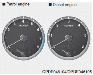
Gauges and meters
Speedometer
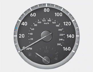
The speedometer indicates the speed of the vehicle and is calibrated in kilometers per hour (km/h) and/or miles per hour (MPH).
Tachometer

Copyright © 2025 www.hi30.net