Hyundai i-30: Air Conditioning System / Compressor
Description and operation
| Description |
The compressor is the power unit of the A/C system.
It is located on the side of engine block and driven by a V-belt of the engine.
The compressor changes low pressure and low temperature refrigerant gas into
high pressure and high temperature refrigerant gas.
Variable Swash Plate Compressor
The compressor has a swash plate that rotates to reciprocate pistons, which
compress refrigerant.
The variable swash plate compressor controls the swash plate angle to change
the refrigerant displacement. It achieves precise cooling capability control
in accordance with vehicle interior and driving conditions.
The externally controlled variable swash plate compressor changes the swash
plate angle by an ECV (Electric Control Valve) in accordance with an electrical
signal from the heater & A/C control unit.
This enables stable temperature control and improved driving sensation.
ECV Control Diagram
Components and components location
| Components Location |
| 1. Compressor |
| Components |
[Gasoline 1.5 MPI]
| 1. Clutch bolt 2. Limiter bolt 3.Disc & Hub assembly 4. Snap ring |
5. Pulley 6. Compressor assembly 7. Electric Control Valve (ECV) 8. Electric Control Valve(ECV) Snap ring |
[Gasoline 1.0 T-GDI, Gasoline 1.5 T-GDI]
| 1. Clutch bolt 2. Disc & Hub assembly 3. Air gap spacer 4. Snap ring 5. Pulley |
6. Field coil
assembly 7. Compressor assembly 8. Electric Control Valve (ECV) 9. Electric Control Valve(ECV) Snap ring |
[Gasoline 1.0 T-GDI MHEV]
| 1. Clutch bolt 2. Disc & Hub assembly 3. Air gap spacer 4. Snap ring 5. Pulley |
6. Field coil
assembly 7. Compressor assembly 8. Electric Control Valve (ECV) 9. Electric Control Valve(ECV) Snap ring |
[Gasoline 1.5 T-GDI MHEV]
| 1. Clutch bolt 2. Disc & Hub assembly 3. Air gap spacer 4. Snap ring 5. Pulley |
6. Field coil
assembly 7. Compressor assembly 8. Electric Control Valve (ECV) 9. Electric Control Valve(ECV) Snap ring |
[Diesel 1.6 VGT]
| 1. Clutch bolt 2. Disc & Hub assembly 3. Air gap spacer 4. Snap ring 5. Pulley |
6. Field coil
assembly 7. Compressor assembly 8. Electric Control Valve (ECV) 9. Electric Control Valve(ECV) Snap ring |
[Diesel 1.6 VGT MHEV]
| 1. Clutch bolt 2. Disc & Hub assembly 3. Air gap spacer 4. Snap ring 5. Pulley |
6. Field coil
assembly 7. Compressor assembly 8. Electric Control Valve (ECV) 9. Electric Control Valve(ECV) Snap ring |
Repair procedures
| Removal |
Precautions for using the plastic pulley
|

| 1. |
If the compressor is marginally operable, run the engine at idle speed,
and let the air conditioning work for a few minutes, then shut the engine
off.
|
| 2. |
Disconnect the negative (-) battery terminal.
|
| 3. |
Recover the refrigerant with a recovery/charging station.
|
| 4. |
Remove the engine room cover.
(Refer to Engine Mechanical System - "Engine Room Cover")
|
| 5. |
Loosen the drive belt.
(Refer to Engine Mechanical System - "Drive Belt")
|
| 6. |
Remove the bolts, then disconnect the suction line (A) and discharge
line (B) from the compressor.
|
| 7. |
Disconnect the compressor switch connector (A).
|
| 8. |
Remove the compressor (A) by loosening the mounting bolts.
|
| Installation |
| 1. |
Make sure the compressor (A) mounting bolt with the correct length is
screwed in. Tighten the mounting bolts with the specified tightening
order.
[Gasoline 1.5 MPI]
[Gasoline 1.0 T-GDI, Gasoline 1.5 T-GDI]
[Gasoline 1.0 T-GDI MHEV]
[Gasoline 1.5 T-GDI MHEV]
[Diesel 1.6 VGT]
[Diesel 1.6 VGT MHEV]
|
| 2. |
To install, reverse the removal procedure.
|
| Inspection |
| 1. |
Check the plated parts of the limiter & hub assembly for color changes,
peeling or other damage. If there is damage, replace the assembly.
|
| 2. |
Check the pulley (A) bearing play and drag by rotating the pulley by
hand. Replace the pulley with a new one if it is noisy or has excessive
play / drag.
|
| External Control Valve Compressor Inspection (GDS) |
Compressor type: Fixed type compressor, External control valve, Internal control
valve.
In cases of fixed type and internal control valve, it is possible to inspect
compressor's operation with clutch noise.
When it comes to External control valve, however, it cannot be checked in this
way bacause it doesn't have a clutch.
So, ECV should be inspected with GDS as below.
| 1. |
Connect GDS to the vehicle and select 'Aircon Compressor Test (ECV type)'
[ECV1]
|
| 2. |
Make the vehicle ready as the GDS instruction on the monitor. (Turn
off A/C 'switch' only)
[ECV2]
[ECV3]
|

| 3. |
Check if other DTC codes are found before inspect ECV compressor. If
so, solve that problems first. If not, press 'OK' button to continue.
[ECV4]
|

| 4. |
Start inspection
[ECV5]
[ECV6]
|


| 5. |
Check the result of inspection and click 'Check Detail' if it's 'Check'.
Follow the instruction and inspect ECV again from the first step.
[ECV7]
[ECV8]
|
| Disassembly |
| 1. |
Remove the engine room under cover.
(Refer to Engine Mechanical System - "Engine Room Cover")
|
| 2. |
Remove the front wheel guard.
(Refer to Body - "Front Wheel Guard")
|
| 3. |
Loosen the drive belt.
(Refer to Engine Mechanical System - "Drive Belt")
|
| 4. |
Remove the clutch bolt while holding the pulley with a clutch bolt remover
(09977-3R000).
|
| 5. |
Loossen the limiter bolts and then remove the limiter & hub assembly.
|
| 6. |
Remove the pulley (B) after removing the snap ring (A) with a snap ring
plier.
|
| 7. |
Reassemble in the reverse order of disassembly.
|
 Refrigerant Line
Components and components location
Components Location
1. Suction &
Liquid tube assembly
Repair procedures
Replacement
1...
 Condenser
Components and components location
Components Location
1. Condenser
Repair procedures
Inspection
1...
Other information:
Hyundai i30 (PD) 2018-2025 Service Manual: ABS Control Module
Components and components location Components [LHD] 1. Front - right tube 2. Rear - left tube 3. Rear - right tube 4. Front - left tube 5. MC SEC 6. MC PRI 7. ABS Control module (HECU) 8...
Hyundai i30 (PD) 2018-2025 Service Manual: Components and positions
..
Categories
- Manuals Home
- 3rd Generation i30 Owners Manual
- 3rd Generation i30 Service Manual
- To activate the ISG system
- Engine coolant
- Light bulbs
- New on site
- Most important about car
Seat belt warning light
Seat belt warning
Driver’s seat belt warning
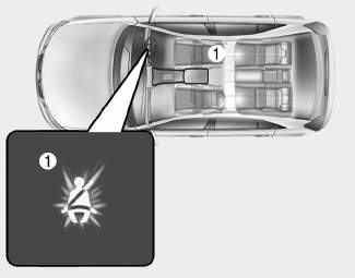
■ Instrument cluster
As a reminder to the driver, the seat belt warning light will illuminate for approximately 6 seconds each time you turn the ignition switch ON regardless of belt fastening.

Copyright © 2025 www.hi30.net