Hyundai i-30: Air Conditioning System / Refrigerant Line
Components and components location
| Components Location |
| 1. Suction &
Liquid tube assembly |
Repair procedures
| Replacement |
| 1. |
If the compressor is marginally operable, run the engine at idle speed,
and let the air conditioning work for a few minutes, then shut the engine
off.
|
| 2. |
Disconnect the negative (-) battery terminal.
|
| 3. |
Recover the refrigerant with a recovery / charging station.
|
| 4. |
Remove the cowl top cover.
(Refer to Body (Interior and Exterior) - "Cowl Top Cover")
|
| 5. |
Remove the bolts and the expansion valve (A) from the evaporator core.
|
| 6. |
Remove the 2 nuts, and then disconnect the discharge line (B) and liquid
line (A) from the condenser.
|
| 7. |
Disconnect the A/C pressure transducer connector (A).
|
| 8. |
Remove the engine room under cover.
(Refer to Engine Mechanical System - "Engine Cover")
|
| 9. |
Remove the bolts, then disconnect the suction line (A) and discharge
line (B) from the compressor.
|

| 10. |
Loosen the bracket mounting bolt (B) from suction& liquid assembly (A).
|
| 11. |
Remove the suction & liquid tube assembly (A) to the upper of engine
room.
|
| 12. |
To install, reverse the removal procedure.
|

 Compressor oil
Repair procedures
Oil Specification
1.
The oil used to lubricate the compressor circulates with the refrigerant.
2...
 Compressor
Description and operation
Description
The compressor is the power unit of the A/C system.
It is located on the side of engine block and driven by a V-belt of the engine...
Other information:
Hyundai i30 (PD) 2018-2025 Owner's Manual: Other LCD display messages
Heated Steering Wheel turned off (if equipped) This message is displayed if you turn off the heated steering wheel. For more details, refer to “Heated Steering Wheel” in this chapter. Low washer fluid (if equipped) This warning message is displayed if the washer fluid level in the reservoir is nearly empty...
Hyundai i30 (PD) 2018-2025 Service Manual: Heated Steering wheel
Components and components location Components location (1) Heated steering wheel switch 1. Heated steering switch Heated steering wheel control module (Body control moduel(BCM)) 1...
Categories
- Manuals Home
- 3rd Generation i30 Owners Manual
- 3rd Generation i30 Service Manual
- Cruise control
- EPB malfunction indicator
- Engine compartment
- New on site
- Most important about car
Air bag - supplemental restraint system
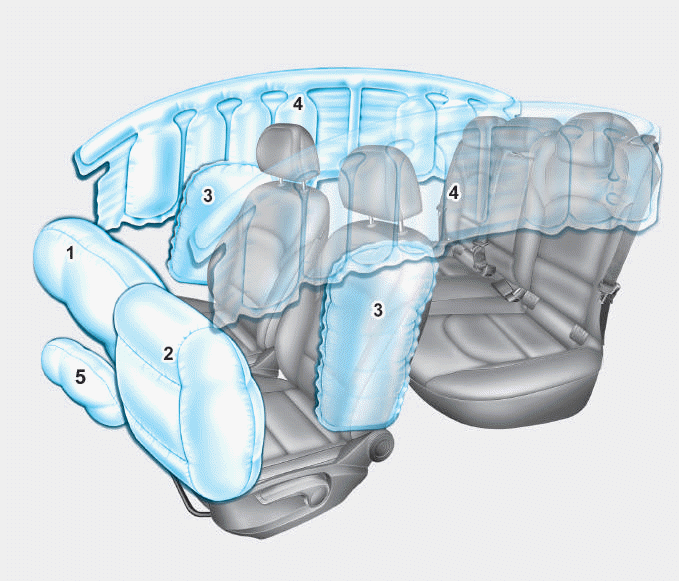
1. Driver’s front air bag
2. Passenger’s front air bag
3. Side air bag*
4. Curtain air bag*
5. Knee air bag*
6. Front passenger air bag ON/OFF
switch

Copyright © 2025 www.hi30.net