Hyundai i-30: Dual Clutch Transmission Assembly / DCT (Dual Clutch Transmission)
Hyundai i30 (PD) 2018-2025 Service Manual / DCT(Dual Clutch Transmission) System / Dual Clutch Transmission Assembly / DCT (Dual Clutch Transmission)
Components and components location
| Components |
| 1. DCT (Dual
Clutch Transmission) assembly 2. DCT support bracket |
3. Roll rod support
bracket |
Repair procedures
| Removal |
| 1. |
Turn ignition switch OFF and disconnect the battery negative (-) terminal.
|
| 2. |
Remove the air cleaner assembly and air duct.
(Refer to Engine Mechnical System - "Air Cleaner")
|
| 3. |
Remove the battery and battery tray.
(Refer to Engine Electrical System - "Battery")
|
| 4. |
Remove the ECM.
(Refer to Engine Control System - "ECM")
|
| 5. |
Disconnect the connectors in the illustration below after loosening
the bracket mounting bolt.
|
| 6. |
Loosen the wiring bracket mounting bolt (A).
|
| 7. |
Loosen the ground mounting bolt (A)
|

| 8. |
Remove the shift cable (C) after loosening the nut (A) and bolts (B).
|
| 9. |
Loosen the mounting bolts and then remove the crankshaft position sensor
(A).
|
| 10. |
Loosen the crankshaft position sensor wiring bracket mounting bolt (A).
|
| 11. |
Loosen the transmission upper mounting bolts (A) and starter mounting
bolts (B).
|
| 12. |
Remove the cowl top cover.
(Refer to Body - "Cowl Top Cover")
|
| 13. |
Install the special service tool (09200-K6100).
(In case of gasoline 1.5 T-GDI)
|
| 14. |
Assemble the engine support fixture (beam No. : 09200-38001 or 09200-3N000,
supporter No. : 09200-2S000, adapter No. : 09200-2W000).
(Refer to Special Service Tools - "Engine Support Fixture Assembly Drawing")
|
| 15. |
Using the engine support fixture(A), hold the engine and transaxle assembly
safely.
|
| 16. |
Remove the cover (A).
|
| 17. |
Remove the transaxle mounting bracket bolts (A).
|
| 18. |
Remove the transmission support bracket (A) after loosening the mounting
bolts.
|
| 19. |
Remove the engine room under cover.
(Refer to Engine Mechanical System - "Engine Room Under Cover")
|
| 20. |
Loosen the ground and bracket mounting bolt (A).
|
| 21. |
Remove the intercooler inlet pipe (A).
|
| 22. |
Remove the roll rod bracket (A) after removing the bolt (B) and (C).
|
| 23. |
Remove the roll rod mounting support bracket (A).
|
| 24. |
Remove the sub frame.
(Refer to Suspension System - "Sub Frame")
|
| 25. |
Remove the front drive shaft assembly.
(Refer to Driveshaft and Axle - "Front Driveshaft")
|
| 26. |
Support the transmission safely by using the jack.
|
| 27. |
Loosen the transmission lower mounting bolts (A, B).
|
| 28. |
After separating the transmission from the engine, remove the transmission
by lowering the jack slowly.
|

| Installation |
| 1. |
To install, reverse the removal procedure.
|
Follow the separated each procedure as below according to reinstallation or
replacing with a new dual clutch transmission.
In case of the reinstallation
| 1. |
If the differential oil seal is damaged and oil is leaking, replace
the oil seal with a new one. When installing the new oil seal, use the
special tool (09453-3L240, 09231-H1100).
|
| 2. |
After installing the DCT, check the oil level after refilling the DCT
with oil.
(Refer to DCT (Dual Clutch Transmission) System - "Transmission Gear
Oil")
|
| 3. |
Clear the diagnostic trouble codes (DTC) using the diagnostic tool.
Even though disconnecting the battery negative terminal, the DTCs will
not be cleared. So, be sure to clear the DTCs using the diagnostic tool.
|
In case of the replacing with a new dual clutch transmission.
| 1. |
After replacing the new DCT, it need not oil refill & level check procedure
because oil is already filled with specified quantity inside new DCT.
|
| 2. |
Clear the diagnostic trouble codes (DTC) using the diagnostic tool.
Even though disconnecting the battery negative terminal, the DTCs will
not be cleared. So, be sure to clear the DTCs using the diagnostic tool.
|
| 3. |
Perform clutch characteristics input procedure using the diagnostic
tool. (One of two procedure must be performed.)
|

 Transmission Gear Oil
General information
General Information
1.
Check & Change intervals
Check & Replenishmen
Change
Capacity
Oil specification
Normal Use
Severe Use
No check
No service required
120000 km
(80000 miles)
1...
Other information:
Hyundai i30 (PD) 2018-2025 Service Manual: Components and components location
..
Hyundai i30 (PD) 2018-2025 Service Manual: Fuel Filler Cap
Description and operation Description A ratchet tightening device on the threaded fuel filler cap reduces the chances of incorrect installation, which would seal the fuel filler. After the gasket on the fuel filler cap and the filler neck flange contact each other, the ratchet produces a loud clicking noise indicating the seal has been set...
Categories
- Manuals Home
- 3rd Generation i30 Owners Manual
- 3rd Generation i30 Service Manual
- Theft-alarm system
- EPB malfunction indicator
- LKA system operation
- New on site
- Most important about car
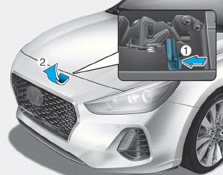
Bonnet
Opening the bonnet
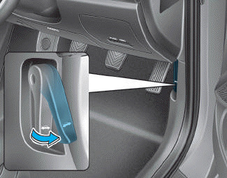
1. Park the vehicle and set the parking brake.
2. Pull the release lever to unlatch the bonnet. The bonnet should pop open slightly.

Copyright © 2025 www.hi30.net