Hyundai i-30: Ignition Lock Switch / Description and operation
Hyundai i30 (PD) 2018-2025 Service Manual / Clutch System / Ignition Lock Switch / Description and operation
| Description |
| – |
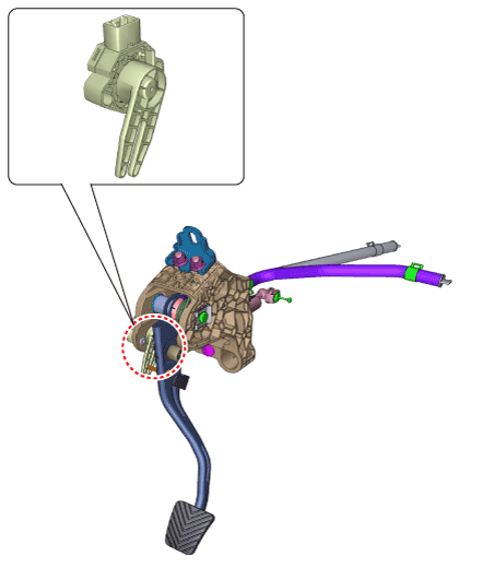
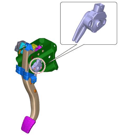
Ignition lock switch is mounted on the clutch pedal.
|
| – |
Ignition lock switch is operated when you press the clutch pedal.
|
| – |
If the clutch pedal is not pressed down, the engine is not started.
|
[Manual Transaxle Type]

[Intelligent Manual Transaxle Type]

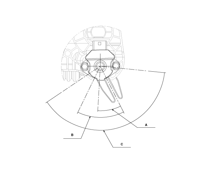
| Ignition lock & clutch switch operating locus [Manual Transaxle Type] |
| – |
If the clutch pedal is pressed down, (B) operate ignition lock switch
at a location.
|
|||||||||||||||||||||||||
 Specifications
Specifications
Item
Specifications
Working voltage
DC 12.5V ± 0.3V
Operating force
Initial position : 0...
 Repair procedures
Removal
[Manual Transaxle Type]
1.
Turn ignition switch OFF and disconnect the negative (-) battery cable...
Other information:
Hyundai i30 (PD) 2018-2025 Service Manual: Description and operation
Description This specification applies to HCU (Hydraulic Control Unit) and ECU (Electronic Control Unit) of the HECU. (Hydraulic and Electronic Control Unit) This specification is for the wiring design and installation of ABS ECU...
Hyundai i30 (PD) 2018-2025 Service Manual: General safety information and caution
Instructions (R-134a) When Handling Refrigerant 1. R-134a liquid refrigerant is highly volatile. A drop on the skin of your hand could result in localized frostbite. When handling the refrigerant, be sure to wear gloves...
Categories
- Manuals Home
- 3rd Generation i30 Owners Manual
- 3rd Generation i30 Service Manual
- Engine coolant
- Tyre pressure monitoring system
- Cruise control
- New on site
- Most important about car
Warning light and message

When the High Beam Assist (HBA)
System is not working properly, the
warning message will come on for a
few second. After the message disappears,
the master warning light ( )
will illuminate.
Copyright © 2025 www.hi30.net

