Hyundai i-30: Engine Control System / Engine Coolant Temperature Sensor (ECTS)
Hyundai i30 (PD) 2018-2025 Service Manual / Engine Control / Fuel System / Engine Control System / Engine Coolant Temperature Sensor (ECTS)
Description and operation
| Description |
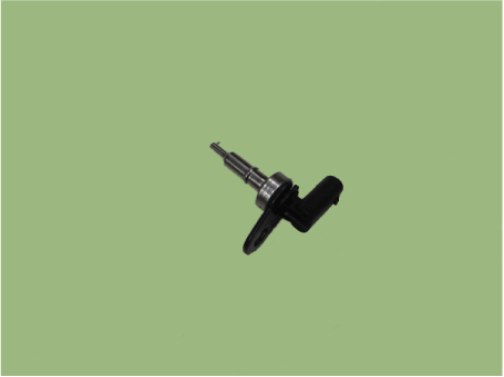
The Engine Coolant Temperature Sensor (ECTS) is located in the cylinder block
and cylinder head, and measures the temperature of the engine coolant.
The thermistor of the cooling water temperature and resistance has a negative
temperature coefficient (NTC) where the resistance decreases when the temperature
rises and the resistance increases when the temperature decreases.
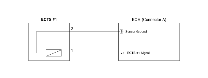
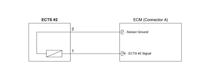
The ECTS # 1 mounted on the cylinder head measures the coolant temperature from
the engine, and the ECTS # 2 mounted on the cylinder block measures the coolant
temperature entering the engine. The ECTS # 1 and the ECTS # 2 deliver the cooling
water temperature to the ECM (Engine Control Module), which delivers the signal
to the Thermal Management Module valve (TMM).
The TMM that receives the signal controls the flow of coolant to adjust the
coolant temperature. In addition, the ECTS calibrates the fuel injection quantity
and the ignition timing based on the information of the cooling water temperature
to prevent the engine failure and an engine-hunting during a cold start test.
Specifications
| Specification |
|
Temperature |
Resistance (kΩ) |
|
|
°C |
°F |
|
|
-40 |
-40 |
41.74 - 54.54 |
|
-30 |
-22 |
23.54 - 29.94 |
|
-20 |
-4 |
14.13 - 16.83 |
|
-10 |
14 |
8.39 - 10.22 |
|
0 |
32 |
5.28 - 6.29 |
|
10 |
50 |
3.42 - 4.00 |
|
20 |
68 |
2.31 - 2.59 |
|
30 |
86 |
1.55 - 1.86 |
|
40 |
104 |
1.08 - 1.21 |
|
50 |
122 |
0.77 - 0.85 |
|
60 |
140 |
0.56 - 0.61 |
|
70 |
158 |
0.41 - 0.44 |
|
80 |
176 |
0.31 - 0.33 |
|
90 |
194 |
0.23 - 0.25 |
|
100 |
212 |
0.18 - 0.19 |
Schematic diagrams
| Circuit Diagram |
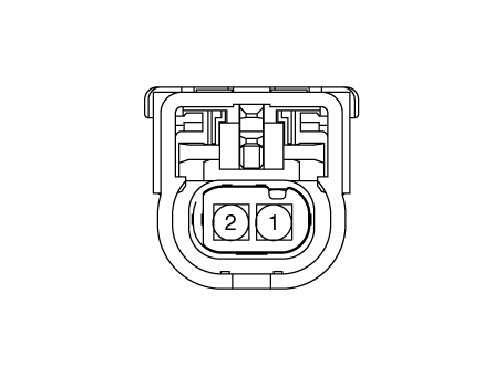
Harness Connector
Repair procedures
| Inspection |
| 1. |
Turn the ignition switch OFF.
|
| 2. |
Remove the ECTS.
(Refer to "Removal")
|
| 3. |
After immersing the thermistor of the sensor into engine coolant, measure
resistance between the ECTS terminals 3 and 4.
|
| 4. |
Check that the resistance is within the specification.
|
| Removal |
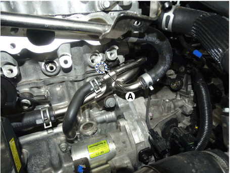
[Engine Coolant Temperature Sensor (ECTS) #1]
| 1. |
Turn the ignition switch OFF, and then disconnect the battery negative
(-) terminal.
|
| 2. |
Remove the delivery pipe.
(Refer to Fuel Delivery System - "Delivery Pipe")
|
| 3. |
Remove the ECTS after loosening the mounting bolt (A).
|
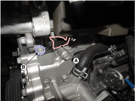
[Engine Coolant Temperature Sensor (ECTS) #2]
| 1. |
Turn the ignition switch OFF, and then disconnect the battery negative
(-) terminal.
|
| 2. |
Remove the alternator.
(Refer to Engine Electrical System - "Alternator")
|
| 3. |
Disconnect the ECTS connector (A).
|
| 4. |
Remove the ECTS after loosening the mounting bolt (B).
|
| Installation |
|

|
|
| 1. |
Install in the reverse order of removal.
|
 EGR Pressure Sensor
Description and operation
Description
The EGR Pressure Sensor is installed on the differential pressure valve and
measures the pressure of the exhaust gas recirculation...
 Crankshaft Position Sensor (CKPS)
Description and operation
Description
Crankshaft Position Sensor (CKPS) detects the crankshaft position and is one
of the most important sensors of the engine control system...
Other information:
Hyundai i30 (PD) 2018-2025 Service Manual: Turbo Charger
Components and components location Comoinents 1. Heat protector 2. DPV assy 3. Turbine housing 4. Compressor housing 5. Compressor inlet 6. EGR outlet hose 7. Center housing 8. Electric waste gate actuator (EWGA) 9...
Hyundai i30 (PD) 2018-2025 Owner's Manual: ISOFIX anchorage and top-tether anchorage (ISOFIX anchorage system) for children
The ISOFIX system holds a Child Restraint System during driving and in an accident.This system is designed to make installation of the Child Restraint System easier and reduce the possibility of improperly installing your Child Restraint System...
Categories
- Manuals Home
- 3rd Generation i30 Owners Manual
- 3rd Generation i30 Service Manual
- Tyre pressure monitoring system
- Brake/clutch fluid
- Drive mode integrated control system
- New on site
- Most important about car
Turn signals and lane change signals
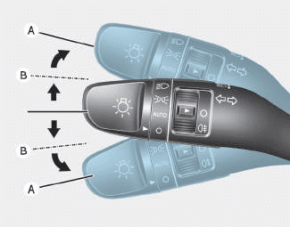
To signal a turn, push down on the lever for a left turn or up for a right turn in position (A). To signal a lane change, move the turn signal lever slightly and hold it in position (B).The lever will return to the OFF position when released or when the turn is completed.

Copyright © 2025 www.hi30.net