Hyundai i-30: Brake System / Front Disc Brake
Components and components location
| Components |
| 1. Caliper body 2. Guide rod pin 3. Guide rod pin boot 4. Caliper carrier |
5. Pad inner
shim 6. Pad retainer 7. Brake pad 8. Pad return spring |
Repair procedures
| Removal |
| 1. |
Loosen the wheel nuts slightly.
Raise the vehicle, and make sure it is securely supported.
|
| 2. |
Remove the front wheel and tire (A) from front hub.
|
| 3. |
Disconnect the brake hose by loosening the bolt (A).
|
| 4. |
Remove the caliper body by loosening the guided rod bolt.
|
| 5. |
Remove the pad return spring (A).
|

| 6. |
Remove the brake pad.
|
| 7. |
Remove the pad retainer (A).
|
| 8. |
Remove the caliper carrier by loosening the caliper mounting bolts.
|
| 9. |
Loosen the screw and the remove the front disc.
|
| Replacement |
Brake Pad
| 1. |
Loosen the wheel nuts slightly.
Raise the vehicle, and make sure it is securely supported.
|
| 2. |
Remove the front wheel and tire (A) from front hub.
|
| 3. |
Loosen the mounting bolt and then remove the brake hose from the strut
assembly.
|
| 4. |
Down the caliper body by loosening the guided rod bolt
|

| 5. |
Remove the pad return spring (A).
|
| 6. |
Remove the brake pad.
|
| 7. |
Replace the pad retainer (A) with a new one.
|
| 8. |
Replace the brake pad with a new one.
|
| 9. |
Install the pad return spring (A).
|
| 10. |
Use a SST (09581-2T100) when installing the brake caliper assembly.
|
| 11. |
Install the caliper body then tighten the guide rod bolt.
|
| 12. |
Install the brake hose bracket to the front strut assembly.
|
| 13. |
Install the front wheel and tire (A).
|
Guide Rod Pin and Boot
| 1. |
Loosen the wheel nuts slightly.
Raise the vehicle, and make sure it is securely supported.
|
| 2. |
Remove the front wheel and tire (A) from front hub.
|
| 3. |
Remove the caliper body by loosening the guided rod bolt.
|
| 4. |
Remove the guide rod pin (A).
|
| 5. |
Replace the guide rod pin boot (A) with a new one.
|
| 6. |
Install the guide rod pin (A) with a new one.
|
| 7. |
Install the caliper body.
|
| 8. |
Install the front wheel and tire (A).
|
| Inspection |
Front brake disc thickness check
| 1. |
Check the brake pads for wear and fade.
|
| 2. |
Check the brake disc for damage and cracks.
|
| 3. |
Remove all rust and contamination from the surface, and measure the
disc thickness at 24 points, at least, of same distance (5mm) from the
brake disc outer circle.
|
| 4. |
If wear exceeds the limit, replace the discs and pad assembly left and
right of the vehicle.
|
Front Brake Pad Check
| 1. |
Check the pad wear. Measure the pad thickness and replace it, if it
is less than the specified value.
|
| 2. |
Check that grease is applied, to sliding contact points and the pad
and backing metal for damage.
|
Front brake disc runout check
| 1. |
Place a dial gauge about 10mm (0.2 in.) from the outer circumference
of the brake disc, and measure the runout of the disc.
|

| 2. |
If the runout of the brake disc exceeds the limit specification, replace
the disc, and then measure the runout again.
|
| 3. |
If the runout does not exceed the limit specification, install the brake
disc after turning it 180° and then check the runout of the brake disc
again.
|
| 4. |
If the runout cannot be corrected by changing the position of the brake
disc, replace the brake disc.
|
| Installation |
| 1. |
To install, reverse the removal procedure.
|
| 2. |
Use a SST (09581-2T100) when installing the brake caliper assembly.
|
| 3. |
After installing, bleed the brake system.
(Refer to Brake System - "Brake System Bleeding")
(Refer to Brake System - "ABS System Bleeding")
(Refer to Brake System - "ESP System Bleeding")
|
 Brake Pedal
Components and components location
Components
1. Brake member
assembly
2. Stop lamp switch
3. Return spring
4...
 Rear Disc Brake
Components and components location
Components
[With EPB]
1. Caliper body
2. Guide rod pin
3. Guide rod pin boot
4...
Other information:
Hyundai i30 (PD) 2018-2025 Service Manual: Seat Belt Pretensioner (BPT)
Components and components location Components 1. Front Seat Belt Pretensioner. 2. Rear Seat Belt Pretensioner. Description and operation Description The Seat Belt Pretensioners (BPT) are installed inside Center Pillar (LH & RH)...
Hyundai i30 (PD) 2018-2025 Owner's Manual: Emission control system
The emission control system of your vehicle is covered by a written limited warranty. Please see the warranty information contained in the Warranty Booklet in your vehicle. Your vehicle is equipped with an emission control system to meet all applicable emission regulations...
Categories
- Manuals Home
- 3rd Generation i30 Owners Manual
- 3rd Generation i30 Service Manual
- LKA system operation
- Light bulbs
- Scheduled maintenance services
- New on site
- Most important about car
Turn signals and lane change signals
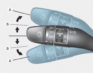
To signal a turn, push down on the lever for a left turn or up for a right turn in position (A). To signal a lane change, move the turn signal lever slightly and hold it in position (B).The lever will return to the OFF position when released or when the turn is completed.

Copyright © 2025 www.hi30.net