Hyundai i-30: Driveshaft Assembly / Front Driveshaft
Hyundai i30 (PD) 2018-2025 Service Manual / Driveshaft and axle / Driveshaft Assembly / Front Driveshaft
Components and components location
| Components |
| 1. Driveshaft
(LH) 2. Dynamic damper |
3. Driveshaft
(RH) |
Repair procedures
| Removal |
| 1. |
Loosen the wheel nuts slightly.
Raise the vehicle, and make sure it is securely supported.
|
| 2. |
Remove the front wheel and tire (A) from the front hub.
|

| 3. |
Loosen the driveshaft caulking nut (A).
|
| 4. |
Remove the tie rod end ball joint.
|
| 5. |
Loosen the lower arm nut (A) and then remove the lower arm ball joint
by using SST (09568-1S100).
|
| 6. |
Remove the driveshaft (A) from the front axle assembly (B).
|
| 7. |
Remove the roll rod stopper (A) by loosening the bolt and nut.
|
| 8. |
Insert a pry bar between the transaxle case and joint case, and separate
the driveshaft from the transaxle case.
[Passenger]
[Driver]
|
| 9. |
To install, reverse the removal procedure.
|
| 10. |
Check the front alignment.
(Refer to Suspension System - "Front Alignment")
|

 TJ Joint
Components and components location
Components
Driver driveshaft
1. BJ assembly
2. BJ circlip
3. BJ boot band
4...
Other information:
Hyundai i30 (PD) 2018-2025 Service Manual: Components and components location
Component Location 1. Smart key unit (SMK) 2. Body control module (BCM) 3. Interior antenna 1 4. Interior antenna 2 5. FOB key 6. Start Stop Button (SSB) 7. Door handle & door antenna 8...
Hyundai i30 (PD) 2018-2025 Owner's Manual: Winter Precautions
Use high quality ethylene glycol coolant Your vehicle is delivered with high quality ethylene glycol coolant in the cooling system. It is the only type of coolant that should be used because it helps prevent corrosion in the cooling system, lubricates the water pump and prevents freezing...
Categories
- Manuals Home
- 3rd Generation i30 Owners Manual
- 3rd Generation i30 Service Manual
- To activate the ISG system
- Drive mode integrated control system
- Cruise control
- New on site
- Most important about car
Warning light and message
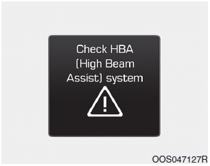
When the High Beam Assist (HBA)
System is not working properly, the
warning message will come on for a
few second. After the message disappears,
the master warning light ( )
will illuminate.
)
will illuminate.

Copyright © 2025 www.hi30.net