Hyundai i-30: Front Suspension System / Front Lower Arm
Hyundai i30 (PD) 2018-2025 Service Manual / Suspension System (NON-ECS) / Front Suspension System / Front Lower Arm
Repair procedures
| Removal |
| 1. |
Loosen the wheel nuts slightly.
Raise the vehicle, and make sure it is securelysupported.
|
| 2. |
Remove the front wheel and tire (A) from the fronthub.
|

| 3. |
Loosen the lower arm nut (A) and then remove thelower arm ball joint
by using SST (09568-1S100).
|
| 4. |
Remove the front lower arm after loosening the bolts& nuts.
|
| 5. |
To install, reverse the removal procedure.
|
| 6. |
Check the wheel Alignment.
(Refer to Tires/Wheels - "Alignment")
|
| Inspection |
| 1. |
Check the bushing for wear and deterioration.
|
| 2. |
Check the lower arm for deformation.
|
| 3. |
Check the all bolts and nuts.
|
| Replacement |
| Ball joint assembly replacement |
| 1. |
Loosen the wheel nuts slightly.
Raise the vehicle, and make sure it is securely supported.
|
| 2. |
Remove the front wheel and tire (A) from the front hub.
|
| 3. |
Loosen the lower arm nut (A) and then remove the lower arm ball joint
by using SST(09568-1S100).
|
| 4. |
Loosen the bolt (A) and (B) then remove the ball joint assembly.
|
| 5. |
Replace the ball joint assembly.
|
| 6. |
Check the wheel Alignment.
(Refer to Tires / Wheels - "Alignment")
|
 Front Strut Assembly
Components and components location
Components
1. Strut assembly
2. Lock nut
3. Insulator
4. Strut bearing & Spring upper pad
5...
 Front Stabilizer Bar
Repair procedures
Removal
1.
Loosen the wheel nuts slightly.
Raise the vehicle, and make sure it is securely supported...
Other information:
Hyundai i30 (PD) 2018-2025 Service Manual: Components and components location
..
Hyundai i30 (PD) 2018-2025 Service Manual: Special service tools
Special Service Tools Tool (Number and Name) Illustration Use Deployment tool 0957A-34100A Airbag deployment tool. Use with (0957A-AL140 and 0957A-AL160) Dummy 0957A-38200 Simulator to check the resistanceof each wiring harness...
Categories
- Manuals Home
- 3rd Generation i30 Owners Manual
- 3rd Generation i30 Service Manual
- Drive mode integrated control system
- Cruise control
- EPB malfunction indicator
- New on site
- Most important about car
Seat belt warning light
Seat belt warning
Driver’s seat belt warning
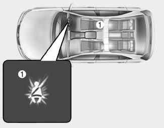
■ Instrument cluster
As a reminder to the driver, the seat belt warning light will illuminate for approximately 6 seconds each time you turn the ignition switch ON regardless of belt fastening.

Copyright © 2025 www.hi30.net