Hyundai i-30: Front Suspension System / Front Strut Assembly
Hyundai i30 (PD) 2018-2025 Service Manual / Suspension System (NON-ECS) / Front Suspension System / Front Strut Assembly
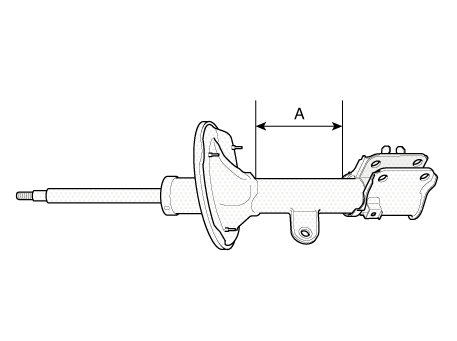
Components and components location
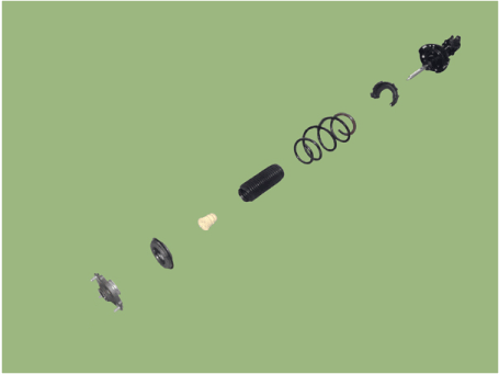
| Components |
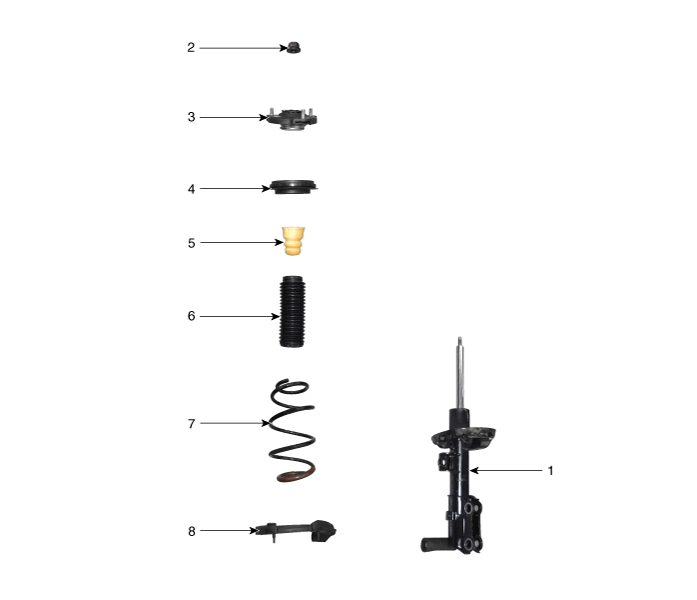
| 1. Strut assembly 2. Lock nut 3. Insulator 4. Strut bearing & Spring upper pad |
5. Bumper rubber 6. Dust cover 7. Coli spring 8. Spring lower pad |
Repair procedures
| Removal |
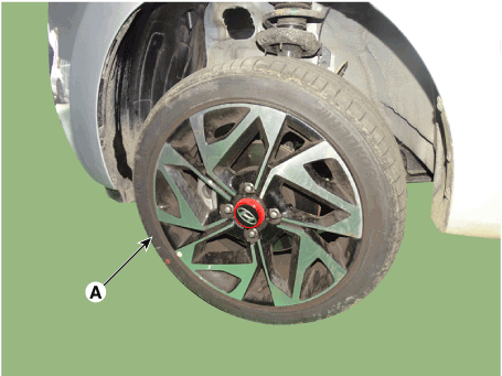
| 1. |
Loosen the wheel nuts slightly.
Raise the vehicle, and make sure it is securelysupported.
|
| 2. |
Remove the front wheel and tire (A) from the fronthub.
|

| 3. |
Loosen the mounting holt and then remove the brakehose from the strut
assembly.
|
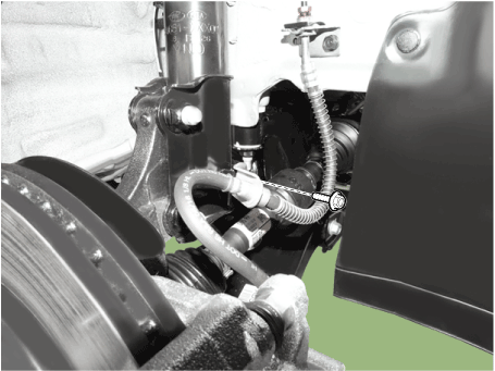
| 4. |
Loosen the mounting holt and then remove the wheelspeed sensor cable
from the strut assembly.
|
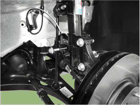
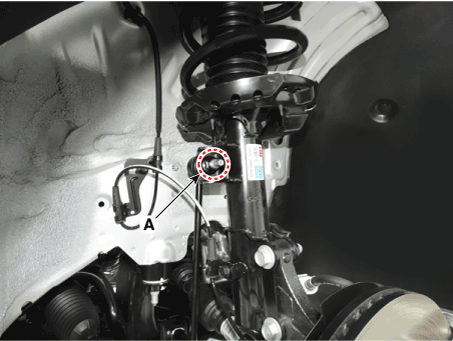
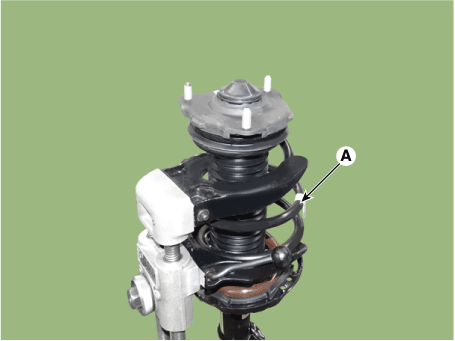
| 5. |
Disconnect the stabilizer link with the front strut assembly after loosening
the nut (A).
|
| 6. |
Remove the cowl top cover.
(Refer to Body - "Cowl Top Cover")
|
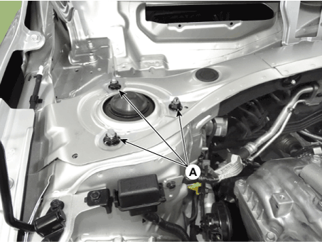
| 7. |
Loosen the upper strut mounting nut (A).
|
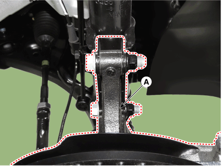
| 8. |
Disconnect the front strut assembly (A) with the frontaxle (B) by loosening
the bolts & nuts.
|
| 9. |
To install, reverse the removal procedure.
|
| Disassembly |
|

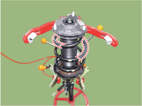
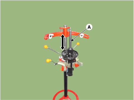
| 1. |
Using spring comperssor, compress the coil spring(A)
|
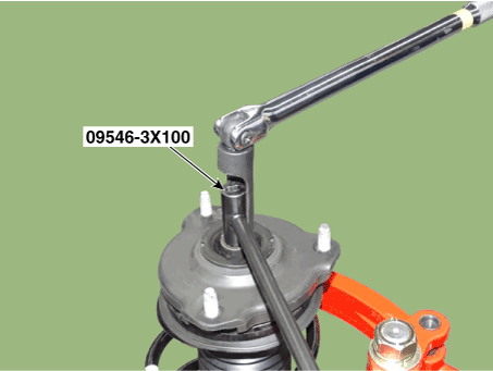
| 2. |
Using the special tool (09546-3X100), remove theself locking nut.
|
| 3. |
Disassembly the strut assembly.
|
| Inspection |
| 1. |
Check the strut bearing for wear and damage.
|
| 2. |
Check the spring upper and lower pad for damageand deterioration.
|
| 3. |
Compress and extend the piston rod (A) and checkthat there is no abnormal
resistance or unusualsound during operation.
|
| Disposal |
| 1. |
Fully extend the piston rod.
|
| 2. |
Drill a hole on the (A) section to remove gas from thecylinder.
|

| Reassembly |
| 1. |
To reassembly, reverse the disassembly procedure.
|
| 2. |
Using the spring compressor,compress the coilspring (A).
|
| 3. |
Using the special tool (09546-3X100), install the selflocking nut.
|
 Components and components location
Components Location
LHD
1. Front strut
assembly
2. Drive shaft
3. Steering gearbox
4. Lower arm
5...
 Front Lower Arm
Repair procedures
Removal
1.
Loosen the wheel nuts slightly.
Raise the vehicle, and make sure it is securelysupported...
Other information:
Hyundai i30 (PD) 2018-2025 Service Manual: Wireless Power Charging Unit
Components and positions Components Circuit diagram Circuit Diagram Repair procedures Removal Handling wireless charging system parts by wet hands may cause electric shock...
Hyundai i30 (PD) 2018-2025 Service Manual: Temperature Control Actuator
Components and components location Components Location 1. Temperature control actuator [LH] 2. Temperature control actuator [RH] Description and operation Description The temperature control actuator is located at the heater unit...
Categories
- Manuals Home
- 3rd Generation i30 Owners Manual
- 3rd Generation i30 Service Manual
- Exhaust System (DPF) Warning Light. Glow Indicator Light
- Auto door lock/unlock features
- Recommended lubricants and capacities
- New on site
- Most important about car
Air bag - supplemental restraint system
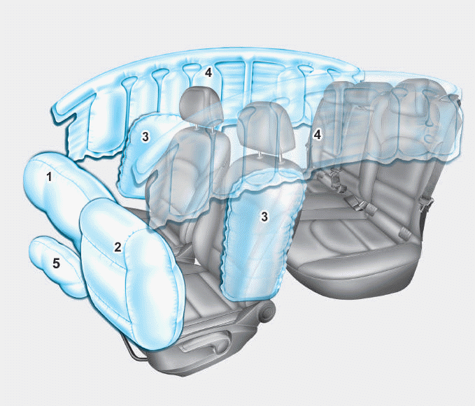
1. Driver’s front air bag
2. Passenger’s front air bag
3. Side air bag*
4. Curtain air bag*
5. Knee air bag*
6. Front passenger air bag ON/OFF
switch

Copyright © 2025 www.hi30.net