Hyundai i-30: General Information / General information
Hyundai i30 (PD) 2018-2025 Service Manual / Body Electrical System / General Information / General information
| General Troubleshooting Information |
Before Troubleshooting
| 1. |
Check applicable fuses in the appropriate fuse/relay box.
|
| 2. |
Check the battery for damage, state of charge, and cleanness and tight
connections.
(Refer to Engine Electrical System - "Battery")
|

| 3. |
Check the alternator belt tension (D).
|
Handling Connectors
| 1. |
Make sure the connectors are clean and have no loose wire terminals.
|
| 2. |
Make sure multiple cavity connectors are packed with grease (except
watertight connectors).
|
| 3. |
All connectors have push-down release type locks (A).
|
| 4. |
Some connectors have a clip on their side used to attach them to a mount
bracket on the body or on another component. This clip has a pull type
lock.
|
| 5. |
Some mounted connectors cannot be disconnected unless you first release
the lock and remove the connector from its mount bracket (A).
|
| 6. |
Never try to disconnect connectors by pulling on their wires; pull on
the connector halves instead.
|
| 7. |
Always reinstall plastic covers.
|
| 8. |
Before connecting connectors, make sure the terminals (A) are in place
and not bent.
|
| 9. |
Check for loose retainer (A) and rubber seals (B).
|
| 10. |
The backs of some connectors are packed with grease. Add grease if necessary.
If the grease (A) is contaminated, replace it.
|
| 11. |
Insert the connector all the way and make sure it is securely locked.
|
| 12. |
Position wires so that the open end of the cover faces down.
|
Handling Wires and Har7nesses
| 1. |
Secure wires and wire harnesses to the frame with their respective wire
ties at the designated locations.
|
| 2. |
Remove clips carefully; don't damage their locks (A).
|
| 3. |
Slip pliers (A) under the clip base and through the hole at an angle,
and then squeeze the expansion tabs to release the clip.
|
| 4. |
After installing harness clips, make sure the harness doesn't interfere
with any moving parts.
|
| 5. |
Keep wire harnesses away from exhaust pipes and other hot parts, from
sharp edges of brackets and holes, and from exposed screws and bolts.
|
| 6. |
Seat grommets in their grooves properly (A). Do not leave grommets distorted
(B).
|
Testing and Repairs
| 1. |
Do not use wires or harnesses with broken insulation.
Replace them or repair them by wrapping the break with electrical tape.
|
| 2. |
After installing parts, make sure that no wires are pinched under them.
|
| 3. |
When using electrical test equipment, follow the manufacturer's instructions
and those described in this manual.
|
| 4. |
If possible, insert the remover tool from the wire side (except waterproof
connector).
|
| 5. |
Use a probe with a tapered tip.
Refer to the user's guide in the wiring repair kit. (Pub No. : TRK 015)
|
Five-step Troubleshooting
| 1. |
Verify the complaint
Turn on all the components in the problem circuit to verify the customer
complaint. Note the symptoms. Do not begin disassembly or testing until
you have narrowed down the problem area.
|
| 2. |
Analyze the schematic
Look up the schematic for the problem circuit.
Determine how the circuit is supposed to work by tracing the current
paths from the power feed through the circuit components to ground.
If several circuits fail at the same time, the fuse or ground is a likely
cause.
Based on the symptoms and your understanding of the circuit operation,
identify one or more possible causes of the problem.
|
| 3. |
Isolate the problem by testing the circuit.
Make circuit tests to check the diagnosis you made in step 2. Keep in
mind that a logical, simple procedure is the key to efficient troubleshooting.
Test for the most likely cause of failure first. Try to make tests at
points that are easily accessible.
|
| 4. |
Fix the problem
Once the specific problem is identified, make the repair. Be sure to
use proper tools and safe procedures.
|
| 5. |
Make sure the circuit works
Turn on all components in the repaired circuit in all modes to make
sure you've fixed the entire problem. If the problem was a blown fuse,
be sure to test all of the circuits on the fuse. Make sure no new problems
turn up and the original problem does not recur.
|
Installation of the transmitting device
Electronic-controlled computers are designed not to interrupted by other radio
signal but it could be effected even less 25W output of remote-cont roll by
wiring an antenna of it or the cables near the computer. Should follow below
directions.
| 1. |
equip an antenna at the roof or rear-bumber.
|
| 2. |
Antenna cables should keep away over 200mm from the computer or wiring
harness because the antenna cables transmit radio signals.
|
| 3. |
decrease the standing-wave ratio by using proper antennas and cables.
|
| 4. |
Not to install remote-controll with a high output.
|
| 5. |
check the status of a engine by generating radio signals with Idling.
|
Power Window and Sunroof Reset
During open/close the power window, sunroof, battery (-) cable is removed or
installed, or the fuse is replaced initialization of power window should be
performed due to the erasure of default motor value.
|
System |
Resetting |
||||||||||||||||
|
Auto up/down window |
|
||||||||||||||||
|
Panoramaroof |
During open/close the sunroof, battery power is not provided or discharged,
or relavant fuse is replaced, or sunroof is activated using emergency handle,
sunroof should be initialized as follows.
|

Trip computer, Clock and Audio Reset
When reconnecting the battery cable after disconnecting, recharging battery
after discharged or installing the memory fuse located on the driver's side
panel after removing, be sure to reset systems mentioned on the below table.
In addition, when replacing or reinstalling their fuses after removing, they
should be reset according to the below table. Please refer to the below table
when servicing.
|
System |
Resetting |
|
Trip computer |
When the battery is disconnected and reconnected, the set functions of the
trip computer become initialized. So, you need to explain this information
to the customer. |
|
Clock |
Whenever the battery terminals or related fuses are disconnected, you must
reset the time in audio head unit.(Refer to Audio owner's manual) |
|
Audio |
When the battery is disconnected and reconnected, the customer's radio stations
become initialized. So, you need to record the customer's radio stations
prior to service, and after service, set the customer's radio stations into
the audio. |

 Special service tools
Special Service Tools
Illustration
Application
RKE Battery Checker
(09954-2P100)
Measuring the RKE battery voltage...
Other information:
Hyundai i30 (PD) 2018-2025 Owner's Manual: User settings mode
In this mode, you can change the settings of the instrument cluster, doors, lamps, etc. 1. Driver Assistance 2. Door 3. Lights 4. Sound 5. Convenience 6. Service Interval 7. Other Features 8. Reset 1. Driver Assistance • Lane Safety - Lane Departure Warning - Standard LKA - Active LKA To adjust the Lane Keeping Assist (LKA) function • Driver Attention Warning - Off/Normal Sensitivity/High Sensitivity To adjust the sensitivity of the Driver Attention Warning (DAW)...
Hyundai i30 (PD) 2018-2025 Service Manual: Repair procedures
Variant Coding When you need variant coding: – Replace Front View Camera with a new one ※ EOL Variant Coding and calibration required for new replacement Front View Camera Variant Coding Front view camera variant coding makes it possible to operate functions for each vehicle type...
Categories
- Manuals Home
- 3rd Generation i30 Owners Manual
- 3rd Generation i30 Service Manual
- Shift-lock system. Shift-lock release
- Exhaust System (DPF) Warning Light. Glow Indicator Light
- Tyre pressure monitoring system
- New on site
- Most important about car
Gauges and meters
Speedometer
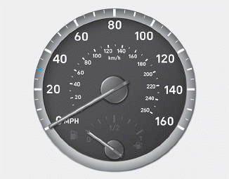
The speedometer indicates the speed of the vehicle and is calibrated in kilometers per hour (km/h) and/or miles per hour (MPH).
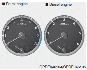
Tachometer

Copyright © 2025 www.hi30.net