Hyundai i-30: Exhaust Emission Control System / GPF (Gasoline Particulate Filter)
Hyundai i30 (PD) 2018-2025 Service Manual / Emission Control System / Exhaust Emission Control System / GPF (Gasoline Particulate Filter)
Description and operation
| Description |
The Gasoline Particulate Filter (GPF) system prevents Particulate Matter (PM)
from being discharged to the atmosphere and consists of a filter assembly, two
Exhaust Gas Temperature Sensors (EGTS). The filter is integrated in the catalytic
converter assembly and has honeycomb cell structure which can filter the PM
in the exhaust gas. While the exhaust gas passes the GPF, This gathered PM in
GPF is called "soot".
Schematic diagrams
| Schematic Diagram |
Repair procedures
| GPF Regeneration |
This procedures is to forcibly regenerate the GPF with scan tool when the GPF
doesn't have been regenerated during driving. For example, if the vehicle has
repeated "Low speed driving" or "Short distance driving", the GPF regeneration
procedure cannot be proceeded because "Regeneration Mode" doesn't made.
|

Forcibly Regeneration Condition
| – |
Engine coolant temperature: about 70°C
|
| – |
Engine at idle
|
| – |
P-range (A/T) or Neutral (M/T)
|
| – |
Normal battery voltage
|
| – |
Electrical fully load ON (A/C ON if equipped, Blower ON with maximum
speed, Head Lamp ON, Wiper ON, Other Lamps ON, etc.).
|
| 1. |
Turn ignition switch OFF.
|
| 2. |
Connect a diagnostic tool to Data Link Connector (DLC).
|
| 3. |
Turn ignition switch ON.
|
| 4. |
Select "Vehicle, Model year, Engine, System".
|
| 5. |
Start engine at idle and P-range (A/T) or neutral (M/T).
|
| 6. |
Apply electrical fully load to the vehicle (A/C ON, Blower ON with maximum
speed, Head Lamp ON, Wiper ON, and Other Lamps ON, etc.).
|
| 7. |
Select "Vehicle S/W Management".
|
| 8. |
Select "GPF Service Regeneration".
|
| Removal |
| 1. |
Turn ignition switch OFF and disconnect the battery (-) terminal.
|
| 2. |
Remove the exhaust gas temperature sensor (EGTS) #1, #2.
(Refer to Engine Control / Fuel System - "Exhaust Gas Temperature Sensor
(EGTS)")
|
| 3. |
Remove the GPF (A).
|
| Installation |
| 1. |
Install in the reverse order of removal.
|

| Replacement |
|
| 1. |
Turn ignition switch OFF.
|
| 2. |
Connect a diagnostic tool to Data Link Connector (DLC).
|
| 3. |
Turn ignition switch ON.
|
| 4. |
Select "Vehicle, Model year, Engine, System".
|
| 5. |
Start engine at idle and P-range (A/T) or neutral (M/T).
|
| 6. |
Apply electrical fully load to the vehicle (A/C ON, Blower ON with maximum
speed, Head Lamp ON, Wiper ON, and Other Lamps ON, etc.).
|
| 7. |
Select "Vehicle S/W Management".
|
| 8. |
Select "Resetting Adaptive Values after GPF replacement".
|
 CVVT (Continuously Variable Valve Timing) System
Description and operation
Description
Continuous variable valve timing (CVVT) system advances or retards the valve
timing of the intake and exhaust valve in accordance with the ECM control signal
which is calculated by the engine speed and load...

Other information:
Hyundai i30 (PD) 2018-2025 Service Manual: Components and components location
..
Hyundai i30 (PD) 2018-2025 Owner's Manual: Low aspect ratio tyres
A low aspect ratio tyre, of which the aspect ratio is lower than 50, is designed for a sporty-look vehicle. The low aspect ratio is to optimize handling and braking. Thus, it may be uncomfortable to ride and it may generate noises, in comparison with a normal tyre...
Categories
- Manuals Home
- 3rd Generation i30 Owners Manual
- 3rd Generation i30 Service Manual
- Light bulbs
- To activate the ISG system
- Brake/clutch fluid
- New on site
- Most important about car
Power windows
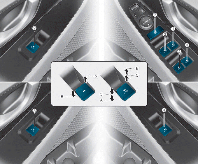
(1) Driver’s door power window
switch
(2) Front passenger’s door power
window switch
(3) Rear door (right) power window
switch
(4) Rear door (left) power window
switch
(5) Window opening and closing
(6) Automatic power window
(7) Power window lock switch

Copyright © 2025 www.hi30.net