Hyundai i-30: Warning and indicator lights / LED Headlamp Warning Light. Cruise Indicator Light. Cruise SET Indicator Light
Hyundai i30 (PD) 2018-2025 Owner's Manual / Convenient features of your vehicle / Instrument cluster / Warning and indicator lights / LED Headlamp Warning
Light. Cruise Indicator Light. Cruise SET Indicator
Light
LED Headlamp Warning Light

This warning light illuminates:
- When you turn the ignition switch or the Engine Start/Stop button to the ON position.
- When there is a malfunction with the LED headlamp.
In this case, we recommend that you have the vehicle inspected by an a HYUNDAI authorised repairer.
This warning light blinks:
When there is a malfunction with a LED headlamp related part.
In this case, we recommend that you have the vehicle inspected by an a HYUNDAI authorised repairer.
NOTICE
Continuous driving with the LED Headlamp Warning Light on or blinking can reduce LED headlamp life.
Cruise Indicator Light

This indicator light illuminates:
• When the cruise control system is enabled.
Cruise SET Indicator Light

This indicator light illuminates:
• When the cruise control speed is set.
 High Beam Assist
(HBA) Indicator Light. Light ON Indicator
Light. Front & Rear Fog Indicator
Light
High Beam Assist
(HBA) Indicator Light. Light ON Indicator
Light. Front & Rear Fog Indicator
Light
High Beam Assist
(HBA) Indicator Light
This warning light illuminates:
When the high-beam is on with the
light switch in the AUTO light position...
 Speed Limiter Indicator
Light. SPORT Mode Indicator
Light. ECO Mode Indicator
Light
Speed Limiter Indicator
Light. SPORT Mode Indicator
Light. ECO Mode Indicator
Light
Speed Limiter Indicator
Light
This indicator light illuminates
when:
• When the speed limiter is enabled.
SPORT Mode Indicator
Light
This indicator light illuminates
• When you select "SPORT" mode
as drive mode...
Other information:
Hyundai i30 (PD) 2018-2025 Service Manual: Instrument Cluster
Components and components location Components TFT LCD Cluster (Standard) TFT LCD Cluster (7Inch) Connector Pin Information Connector Pin Information No. Description No. Description 1 Ground 21 Trip switch (-) 2 Illumination (-) 22 Trip switch 1 (+) 3 Rheostat switch (Down)_Input 23 Trip switch 2 (+) 4 Rheostat switch (Up)_Input 24 M/T N switch 5 Dentent 25 Driver mode switch 6 P 26 - 7 R 27 - 8 N 28 Low washer level sensor 9 D 29 M-CAN (Low) 10 S 30 M-CAN (High) 11 Immobillizer 31 - 12 Vehicle speed_Output 32 C-CAN (High) 13 Alternator_Input 33 C-CAN(Low) 14 Fuel sender (+)_Input 34 - 15 - 35 - 16 Fuel sender (-)_Input 36 - 17 Water separator (+) 37 Ground 18 Airbag (+)_Input 38 - 19 Oil press switch (-)_Input 39 IGN 1 20 Tail_input 40 Battery (+) Schematic diagrams Circuit Diagram TFT LCD Cluster (Standard) TFT LCD Cluster (7Inch) Description and operation Description Communication Network Diagram Abbreviation Expalnation ECM Engine Control Module TCU Transmission Control Unit MDPS Motor Driven Power Steering AEB Autonomous Emergency Braking LKAS Lane Keeping Assist System FPS Fuel Pump Control module RR CAMERA Rear View Carmera VACUUM Vacuum Pump CLUSTER Cluster Module ACU Airbag Control Unit DATC Dual Automatic Temp Control MTC Temp Control OCS Occupant Classification System VDC Vehicle Dynamic Control BSD Blind Spot Detection AMP Amplifier AVN Head Unit (Audio / AVN) SMK Smart Key Unit WPC Wireless Power Charger IMS Integrated Memory System DDM Driver Door Module ADM Assist Door Module BCM Body Control Module B-CAN Body Controller Area Network P-CAN Powertrain Controller Area Network M-CAN Multi media Controller Area Network C-CAN Chassis Controller Area Network Cluster Variant Coding As we have more options (ESC, MDPS etc...
Hyundai i30 (PD) 2018-2025 Service Manual: Power Door Mirror Switch
Components and components location Components Schematic diagrams Circuit Diagram Repair procedures Inspection Power Window Switch 1. Disconnect the negative (-) battery terminal...
Categories
- Manuals Home
- 3rd Generation i30 Owners Manual
- 3rd Generation i30 Service Manual
- Engine coolant
- Auto door lock/unlock features
- Headlamp, static bending lamp, position lamp, turn signal lamp and daytime running light bulb replacement
- New on site
- Most important about car
Tailgate
Opening the tailgate
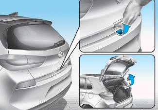
■ 5 Door, Wagon
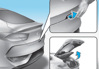
■ Fastback

Copyright © 2025 www.hi30.net