Hyundai i-30: Lubrication System / Oil Pump
Components and components location
| Components |
| 1. Cylinder block 3. Oil pump sproket |
2. Oil pump |
Repair procedures
| Removal And Installation |
Oil Pump
| 1. |
Remove the engine room under cover.
(Refer to Engine and Transaxle Assembly - "Engine Room Under Cover")
|
| 2. |
Drain the engine oil.
(Refer to Lubrication System - "Engine Oil")
|
| 3. |
Remove the oil pan.
(Refer to Lubrication System - "Oil Pan")
|
| 4. |
Turn the oil pump chain tensioner (A) in the direction of the arrow
and remove the oil pump chain and spricket (B) from the oil pump.
|
| 5. |
Remove the oil pump (A).
|
| 6. |
Install in the reverse order of removal.
|
| 7. |
Start engine and check for oil leaks.
|
Oil Pump Chain
| 1. |
Remove the timing chain.
(Refer to Timing System - "Timing Chain")
|
| 2. |
Remove the oil pump chain tensioner arm (A).
|
| 3. |
Remove the oil pump sproket (A) and oil pump chaing (B).
|
| 4. |
Install in the reverse order of removal.
|
| 5. |
Start engine and check for oil leaks.
|
 Engine Oil
Repair procedures
Engine Oil and Filter Replacement
•
Prolonged and repeated contact with mineral oil will result
in the removal of natural fats from the skin, leading to dryness,
irritation and dermatitis...
 Oil Pressure Control Solenoid Valve
Repair procedures
Removal
1.
Disconnect the negative battery terminal.
2.
Disconnect the oil pressure control solenoid valve wiring, and then
remove the oil pressure control solenoid valve (A)...
Other information:
Hyundai i30 (PD) 2018-2025 Service Manual: Front Door Module
Components and components location Component Location 1. Front door module Repair procedures Replacement 1. Remove the front door window glass. (Refer to Front Door - "Front Door Window Glass") 2...
Hyundai i30 (PD) 2018-2025 Owner's Manual: Special driving conditions
Hazardous driving conditions When hazardous driving elements are encountered such as water, snow, ice, mud and sand, take the following precautions: Drive cautiously and maintain a longer braking distance. Avoid abrupt braking or steering...
Categories
- Manuals Home
- 3rd Generation i30 Owners Manual
- 3rd Generation i30 Service Manual
- Exhaust System (DPF) Warning Light. Glow Indicator Light
- Brake/clutch fluid
- Tyre pressure monitoring system
- New on site
- Most important about car
Seat belt warning light
Seat belt warning
Driver’s seat belt warning
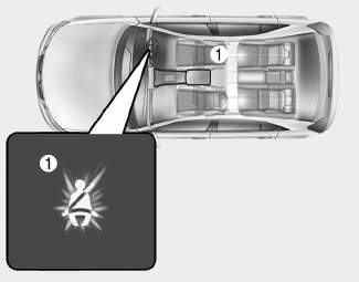
■ Instrument cluster
As a reminder to the driver, the seat belt warning light will illuminate for approximately 6 seconds each time you turn the ignition switch ON regardless of belt fastening.

Copyright © 2025 www.hi30.net