Hyundai i-30: Heater / PTC Heater
Description and operation
| Description |
The PTC (Positive Temperature Coefficient) heater is installed at the exit or
the backside of heater core.
The PTC heater is an electric heater using a PTC element as an auxiliary heating
device that supplements deficiency of interior heat source in highly effective
diesel engine. The electric heater heats up the interior by directly heating
the air that passes through the heater. The name itself implies that the element
has a proportional resistance change sensitive to temperature.
Operation Principle
ECM outputs a PTC ON signal and operates PTC relay 1. Then heater controller
operates PTC relay 2 and PTC relay 3 with an interval of 15 seconds.
However, PTC relay 3 can be operated while battery voltage is above 12.4V.
Operating Condition
PTC heater operates according to the following conditions.
| • |
Battery voltage: 12.4V or above
|
| • |
Engine : Running
|
| • |
Ambient temperature and coolant temperature
|
|
Ambient Temperature |
Coolant Temperature |
PTC Operation |
|
Below -20°C (-4°F) |
Below 75°C (167°F) |
ON |
|
10°C (50°F) |
Below 65°C (149°F) |
ON |
|
12°C (53.6°F) or above |
- |
OFF |
|
- |
80°C (176°F) or above |
OFF |
Repair procedures
| Inspection |
Operating Logic Test (Manual only)
Inspect the PTC operation by confirmation logic as follows;
| 1. |
Entering
|
| 2. |
Cancellation
|
| 3. |
If the PTC is not operated, substitute with a known-good PTC heater
and check for proper operation.
If the problem is corrected, replace the PTC heater.
|
Operating Test
This test should be performed in the PTC ON conditions.
| 1. |
Run the engine.
|
| 2. |
Check the current on wiring with a clamp multi tester.
|
| 3. |
If the current is not specification, inspect related wiring.
|
Resistance Test
| 1. |
Turn the ignition switch OFF.
|
| 2. |
Disconnect the PTC heater connector.
|
| 3. |
Measure the resistance between terminal 1, 2, 3 of PTC heater and ground
line.
[Diesel]
[Gasoline]
|
| 4. |
If the measured resistance is not specification, replace the PTC heater
with new one.
|
| Replacement |
| [Gasoline] |
| 1. |
Disconnect the negative (-) battery terminal.
|
| 2. |
Remove the floor console side cover [LH] (A).
|
| 3. |
Disconnect the PTC heater connector.
|
| 4. |
Remove the PTC heater core (A) after loosening the PTC heater mounting
screws.
|
| 5. |
To install, reverse the removal procedure.
|
| [Diesel] |
| 1. |
Disconnect the negative (-) battery terminal.
|
| 2. |
Remove the floor console side cover [LH] (A).
|
| 3. |
Disconnect the PTC heater connector (A).
|
| 4. |
Remove the PTC heater core (A) after loosening the PTC heater mounting
screws.
|
| 5. |
To install, reverse the removal procedure.
|
 Heater Core
Repair procedures
Replacement
1.
Disconnect the negative (-) battery terminal.
2.
Remove the heater and blower assembly...
 Evaporator Core
Repair procedures
Replacement
1.
Disconnect the negative (-) battery terminal.
2.
Remove the heater and blower assembly...
Other information:
Hyundai i30 (PD) 2018-2025 Owner's Manual: Battery replacement
If the Smart Key is not working properly, try replacing the battery with a new one. Battery Type: CR2032 To replace the battery: 1. Remove the mechanical key. 2. Use a slim tool to pry open the rear cover of the smart key. 3. Remove the old battery and insert the new battery...
Hyundai i30 (PD) 2018-2025 Owner's Manual: Blind-spot collision warning (BCW) system
[A] : Blind spot area [B] : Closing at high speed The Blind-spot Collision Warning (BCW) system uses radar sensors in the rear bumper to monitor and warn the driver of an approaching vehicle in the driver's blind spot area. The system monitors the rear area of the vehicle and provides information to the driver with an audible alert and an indicator on the outside rearview mirrors...
Categories
- Manuals Home
- 3rd Generation i30 Owners Manual
- 3rd Generation i30 Service Manual
- Exhaust System (DPF) Warning Light. Glow Indicator Light
- EPB malfunction indicator
- Shift-lock system. Shift-lock release
- New on site
- Most important about car
Tailgate
Opening the tailgate
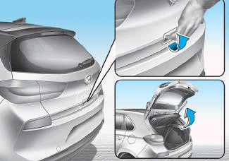
■ 5 Door, Wagon
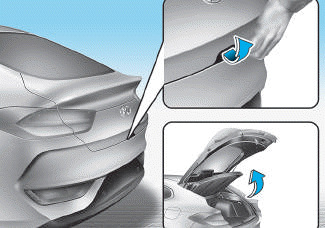
■ Fastback

Copyright © 2025 www.hi30.net