Hyundai i-30: Rear Suspension System / Rear Shock Absorber
Hyundai i30 (PD) 2018-2025 Service Manual / Suspension System (NON-ECS) / Rear Suspension System / Rear Shock Absorber
Components and components location
| Components |
| 1. Shock absorber
dust cap 2. Lock nut 3. Insulator assembly |
4. Bumper rubber 5. Dust cover 6. Shock absorber |
Repair procedures
| Removal |
| 1. |
Loosen the wheel nuts slightly.
Raise the vehicle, and make sure it is securely supported.
|
| 2. |
Remove the rear wheel and tire (A) from the rear hub.
|

| 3. |
Remove the rear shock absorber (A) from the frame by loosening the bolt.
|
| 4. |
Loosen the bolt & nut and then remove the rear shock absorber (A) from
the torsion beam axle.
|
| 5. |
To install, reverse the removal procedure.
|
| Disassembly |
| 1. |
Remove the lock nut cover (A).
|
| 2. |
Using the special tool (09546-3X100), install the self locking nut.
|
| 3. |
Separate the bracket assembly (A), bumper rubber (B), dust cover (C),
shock absorber (D).
|
| Disposal |
| 1. |
Remove the strike cap (A) from the shock absorber assembly.
|
| 2. |
Remove the gas by Drilling a hole in the inner oil seal.
|

| Reassembly |
| 1. |
To reassembly, reverse the disassembly procedure.
|
| 2. |
Using SST (09546-3X100), install the lock nut.
|
| 3. |
Install the lock nut cover (A).
|

 Rear Coil Spring
Components and components location
Components
1. Spring upper
pad
2. Coil spring
3. Spring lower
pad
Repair procedures
Removal
1...
Other information:
Hyundai i30 (PD) 2018-2025 Service Manual: Repair procedures
A/S Repair produres MDPS System A/S Workflow ① Noise / malfunction Inspection ② Warning lamp (DTC) / CAN Line error 2 - 1 Checking Connectors and Wiring 1. Checking Connectors and Wiring...
Hyundai i30 (PD) 2018-2025 Owner's Manual: Heated steering wheel
When the ignition switch is in the ON position or when the engine is running, press the heated steering wheel button to warm the steering wheel. The indicator on the button will illuminate. To turn the heated steering wheel off, press the button again...
Categories
- Manuals Home
- 3rd Generation i30 Owners Manual
- 3rd Generation i30 Service Manual
- Scheduled maintenance services
- Drive mode integrated control system
- Shift-lock system. Shift-lock release
- New on site
- Most important about car
Seat belt warning light
Seat belt warning
Driver’s seat belt warning
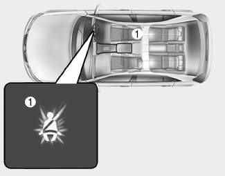
■ Instrument cluster
As a reminder to the driver, the seat belt warning light will illuminate for approximately 6 seconds each time you turn the ignition switch ON regardless of belt fastening.

Copyright © 2025 www.hi30.net