Hyundai i-30: Front Axle Assembly. Front Hub / Knuckle / Repair procedures
Hyundai i30 (PD) 2018-2025 Service Manual / Driveshaft and axle / Front Axle Assembly. Front Hub / Knuckle / Repair procedures
| Removal |
| 1. |
Loosen the wheel nuts slightly.
Raise the vehicle, and make sure it is securely supported.
|
| 2. |
Remove the front wheel and tire (A) from the front hub.
|

| 3. |
Remove the front brake caliper.
(Refer to Brake System - "Front Disc Brake")
|
| 4. |
Loosen the driveshaft caulking nut (A).
|
| 5. |
Remove the tie rod end ball joint.
|
| 6. |
Loosen the screw and then remove the front disc.
|
| 7. |
Loosen the lower arm nut (A) and then remove the lower arm ball joint
by using SST (09568-1S100).
|
| 8. |
Remove the driveshaft (A) from the front axle assembly (B).
|
| 9. |
Loosen the bolt and then remove the wheel speed sensor (A).
|
| 10. |
Remove the hub bearing from the front knuckle.
|
| 11. |
Loosen the mounting bolts and then remova the dust cover.
|
| 12. |
Loosen the strut mounting bolts, nuts and then remove the knuckle assembly.
|
| 13. |
To install, reverse the removal procedure
|
| 14. |
Check the alignment.
(Refer to Suspension System - "Alingment")
|
| Inspection |
| 1. |
Check the hub for cracks and the splines for wear.
|
| 2. |
Check the brake disc for scoring and damage.
|
| 3. |
Check the knuckle for cracks.
|
| 4. |
Check the bearing for cracks or damage.
|


Other information:
Hyundai i30 (PD) 2018-2025 Owner's Manual: EPB malfunction indicator
This warning light illuminates if the Engine Start/Stop button is changed to the ON position and goes off in approximately 3 seconds if the system is operating normally. If the EPB malfunction indicator remains on, comes on whilst driving, or does not come on when the Engine Start/Stop button is changed to the ON position, this indicates that the EPB may have malfunctioned...
Hyundai i30 (PD) 2018-2025 Service Manual: Outside Rear View Mirror
Components and components location Component Location 1. Outside rear view mirror Repair procedures Replacement • Put on gloves to prevent hand injuries...
Categories
- Manuals Home
- 3rd Generation i30 Owners Manual
- 3rd Generation i30 Service Manual
- Brake/clutch fluid
- Theft-alarm system
- LKA system operation
- New on site
- Most important about car
Air bag - supplemental restraint system
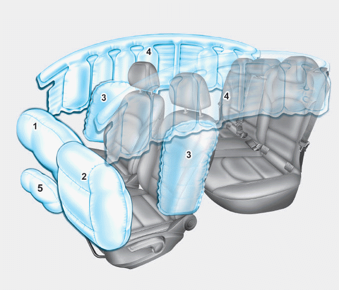
1. Driver’s front air bag
2. Passenger’s front air bag
3. Side air bag*
4. Curtain air bag*
5. Knee air bag*
6. Front passenger air bag ON/OFF
switch

Copyright © 2025 www.hi30.net