Hyundai i-30: ESP (Electronic Stability Program) System / Repair procedures
Hyundai i30 (PD) 2018-2025 Service Manual / Brake System / ESP (Electronic Stability Program) System / Repair procedures
| Inspection |
ESP System Bleeding
This procedure should be followed to ensure adequate bleeding of air and filling
of the ESC unit, brake lines and master cylinder with brake fluid.
| 1. |
Remove the reservoir cap and fill the brake reservoir with brake fluid.
|

| 2. |
Connect a clear plastic tube to the wheel cylinder bleeder plug and
insert the other end of the tube into a half filled clear plastic bottle.
|
| 3. |
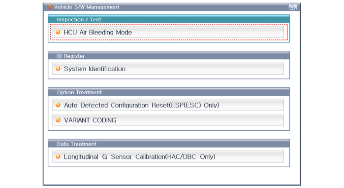
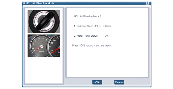
Connect the diagnostic tool to the data link connector located underneath
the dash panel.
|
| 4. |
Select and operate according to the instructions on the diagnostic tool
screen
|
| 5. |
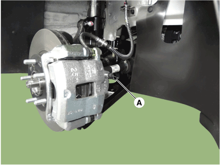
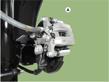
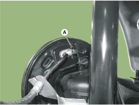
Pump the brake pedal several times, and then loosen the bleeder screw
until fluid starts to run out without bubbles. Then close the bleeder
screw (A).
[Front]
[Rear Disc Brake]
[Rear Durm Brake]
|
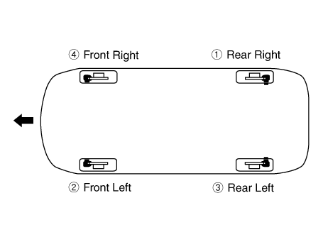
| 6. |
Repeat the procedure for wheel in the sequence shown below until air
bubbles no longer appear in the fluid.
|
| 7. |
Refill the master cylinder reservoir to MAX (upper) level line.
|
 Schematic diagrams
Schematic Diagrams
[Without EPB]
[With EPB]
Terminal Function
[EPB None Apply]
PIN No
Desciption
Current
max
min
1
Voltage supply for pump motor
40A
10 MΩ
2
-
1...
 Troubleshooting
Failure Diagnosis
1.
In principle, ESP and TCS controls are prohibited in case of ABS failure.
2...
Other information:
Hyundai i30 (PD) 2018-2025 Service Manual: AEB Camera
Repair procedures Removal 1. Disconnect the negative (-) battery terminal. 2. Remove the MFC unit cover (A). 3. Disconnect the MFC unit connector (A)...
Hyundai i30 (PD) 2018-2025 Owner's Manual: Headlamp, static bending lamp, position lamp, turn signal lamp and daytime running light bulb replacement
Type A Type B (1) Headlamp (High) (2) Headlamp (Low) (3) Turn signal lamp (4) Daytime running light (if equipped) (5) Position lamp (6) Static bending light WARNING Handle halogen bulbs with care. Halogen bulbs contain pressurized gas that will produce flying pieces of glass that could cause injuries if broken...
Categories
- Manuals Home
- 3rd Generation i30 Owners Manual
- 3rd Generation i30 Service Manual
- Tyre pressure monitoring system
- Scheduled maintenance services
- Engine compartment
- New on site
- Most important about car
Tailgate
Opening the tailgate
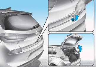
■ 5 Door, Wagon
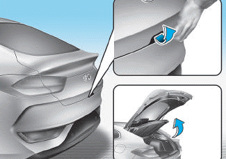
■ Fastback

Copyright © 2025 www.hi30.net