Hyundai i-30: ESP (Electronic Stability Program) System / Schematic diagrams
Hyundai i30 (PD) 2018-2025 Service Manual / Brake System / ESP (Electronic Stability Program) System / Schematic diagrams
| Schematic Diagrams |
[Without EPB]
[With EPB]
| Terminal Function |
[EPB None Apply]
|
PIN No |
Desciption |
Current |
|
|
max |
min |
||
|
1 |
Voltage supply for pump motor |
40A |
10 MΩ |
|
2 |
- |
1.2 mA |
250 MΩ |
|
3 |
- |
- |
- |
|
4 |
C-CAN HIGH |
100 mA |
250 MΩ |
|
5 |
C-CAN LOW |
100 mA |
250 MΩ |
|
6 |
- |
- |
- |
|
7 |
P-CAN LOW |
100 mA |
250 MΩ |
|
8 |
P-CAN High |
100 mA |
250 MΩ |
|
9 |
Wheel speed sensor power voltage (RL) |
100 mA |
250 MΩ |
|
10 |
Wheel speed sensor power voltage (RR) |
100 mA |
250 MΩ |
|
11 |
Wheel speed sensor power voltage (FR) |
100 mA |
250 MΩ |
|
12 |
Wheel speed sensor power voltage (FL) |
100 mA |
250 MΩ |
|
13 |
Recirculation pump ground |
40A |
10 MΩ |
|
14 |
- |
- |
- |
|
15 |
Clutch Switch (MT Only) |
1.2 mA |
250 MΩ |
|
16 |
- |
1.2 mA |
250 MΩ |
|
17 |
ESP Switch |
1.2 mA |
250 MΩ |
|
18 |
- |
- |
- |
|
19 |
Parking brake switch |
1.2 mA |
250 MΩ |
|
20 |
TPMS reset switch signal |
1.2 mA |
250 MΩ |
|
21 |
Wheel speed sensor ground (RL) |
40 mA |
250 MΩ |
|
22 |
Wheel speed sensor ground (RR) |
40 mA |
250 MΩ |
|
23 |
Wheel speed sensor ground (FR) |
40 mA |
250 MΩ |
|
24 |
Wheel speed sensor ground (FL) |
40 mA |
250 MΩ |
|
25 |
Voltage supply for solenoid valves |
30A |
10 MΩ |
|
26 |
Brake pressure sensor ground |
60 mA |
10 MΩ |
|
27 |
Brake pressure sensor signal |
40 mA |
250 MΩ |
|
28 |
Brake pressure sensor power |
60 mA |
10 MΩ |
|
29 |
- |
- |
- |
|
30 |
Brake lamp switch |
1.2 mA |
250 MΩ |
|
31 |
- |
- |
- |
|
32 |
IGN 1 |
10mA |
50MΩ |
|
33 |
- |
- |
- |
|
34 |
- |
- |
- |
|
35 |
- |
- |
- |
|
36 |
- |
- |
- |
|
37 |
Wheel speed sensor output (FR) |
50 mA |
250 MΩ |
|
38 |
Ground for solenoid valves and ECU |
30A |
10 MΩ |
[EPB Apply]
|
PIN No |
Desciption |
Current |
|
|
max |
min |
||
|
1 |
Voltage supply for pump motor |
39A |
10 MΩ |
|
2 |
RR EPB motor power |
30A |
10 MΩ |
|
3 |
RR EPB motor ground |
30A |
10 MΩ |
|
4 |
Brake pressure sensor ground |
60 mA |
10 MΩ |
|
5 |
Clutch stroke sensor |
40 mA |
250 MΩ |
|
6 |
Electric parking brake signal 1 |
20 mA |
250 MΩ |
|
7 |
Electric parking brake signal 2 |
20 mA |
250 MΩ |
|
8 |
Electric parking brake signal 3 |
20 mA |
250 MΩ |
|
9 |
Electric parking brake signal 4 |
20 mA |
250 MΩ |
|
10 |
Brake pressure sensor signal |
40 mA |
250 MΩ |
|
11 |
Brake pressure sensor power |
60 mA |
10 MΩ |
|
12 |
Moc motor ground (Rear left) |
15 A |
10 MΩ |
|
13 |
Moc motor power (Rear left) |
15 A |
10 MΩ |
|
14 |
Ground for solenoid valves and ECU |
30A |
10 MΩ |
|
15 |
- |
- |
- |
|
16 |
- |
- |
- |
|
17 |
ESP OFF switch signal |
1.2 mA |
250 MΩ |
|
18 |
N' Signal |
100 mA |
250 MΩ |
|
19 |
C - CAN High |
100 mA |
250 MΩ |
|
20 |
C - CAN Low |
100 mA |
250 MΩ |
|
21 |
- |
- |
|
|
22 |
P-CAN Low |
100 mA |
250 MΩ |
|
23 |
P-CAN High |
100 mA |
250 MΩ |
|
24 |
- |
- |
250 MΩ |
|
25 |
Wheel speed sensor supply voltage (RL) |
150 mA |
250 MΩ |
|
26 |
Wheel speed sensor supply voltage (RR) |
150 mA |
250 MΩ |
|
27 |
Wheel speed sensor supply voltage (FR) |
150 mA |
250 MΩ |
|
28 |
Wheel speed sensor supply voltage (FL) |
150 mA |
250 MΩ |
|
29 |
- |
16.8 mA |
250 MΩ |
|
30 |
Voltage supply for solenoid valves |
30A |
10 MΩ |
|
31 |
TPMS reset switch signal |
1.2 mA |
250 MΩ |
|
32 |
- |
- |
- |
|
33 |
- |
- |
- |
|
34 |
Auto holding ON/OFF switch signal |
1.2 mA |
250 MΩ |
|
35 |
Brake light switch |
1.2 mA |
250 MΩ |
|
36 |
- |
- |
- |
|
37 |
IGN 1 |
5A |
250 MΩ |
|
38 |
- |
- |
- |
|
39 |
- |
- |
- |
|
40 |
- |
- |
- |
|
41 |
Wheel speed sensor ground (RL) |
40 mA |
250 MΩ |
|
42 |
Wheel speed sensor ground (RR) |
40 mA |
250 MΩ |
|
43 |
Wheel speed sensor ground (FR) |
40 mA |
250 MΩ |
|
44 |
Wheel speed sensor ground (FL) |
40 mA |
250 MΩ |
|
45 |
Wheel speed output (FR) |
50 mA |
250 MΩ |
|
46 |
Recirculation pump ground |
60A |
10 MΩ |
 Description and operation
Description of ESP
Optimum driving safety now has a name : ESP, the Electronic Stability Program.
ESP recognizes critical driving conditions, such as panic reactions in dangerous
situations, and stabilizes the vehicle by wheel-individual braking and engine
control intervention with no needfor actuating the brake or the gas pedal...
 Repair procedures
Inspection
ESP System Bleeding
This procedure should be followed to ensure adequate bleeding of air and filling
of the ESC unit, brake lines and master cylinder with brake fluid...
Other information:
Hyundai i30 (PD) 2018-2025 Owner's Manual: Lane Keeping Assist (LKA) system Indicator Light. Icy Road Warning Light
Lane Keeping Assist (LKA) system Indicator Light This indicator light illuminates: [Green] When the system operating conditions are satisfied. [White] The system operating conditions are not satisfied. [Yellow] When there is a malfunction with the lane keeping assist system...
Hyundai i30 (PD) 2018-2025 Owner's Manual: Tailgate
Opening the tailgate ■ 5 Door, Wagon ■ Fastback Make sure the vehicle is in P (Park) and set the parking brake. Then do one of the following: 1. Unlock all doors with the Door Unlock button on your remote key or smart key. Press the tailgate handle button and open the tailgate...
Categories
- Manuals Home
- 3rd Generation i30 Owners Manual
- 3rd Generation i30 Service Manual
- EPB malfunction indicator
- Scheduled maintenance services
- Trip computer
- New on site
- Most important about car
Gauges and meters
Speedometer
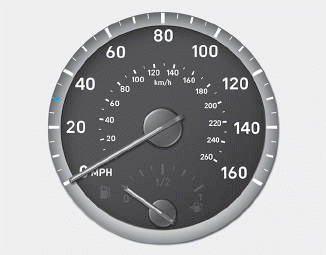
The speedometer indicates the speed of the vehicle and is calibrated in kilometers per hour (km/h) and/or miles per hour (MPH).
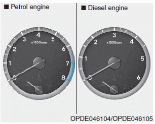
Tachometer

Copyright © 2025 www.hi30.net