Hyundai i-30: ABS (Anti-Lock Brake System) / Schematic diagrams
Hyundai i30 (PD) 2018-2025 Service Manual / Brake System / ABS (Anti-Lock Brake System) / Schematic diagrams
| Schematic Diagrams |
| [Without EPB] |
| [With EPB] |
| Termianal Function |
| [Without EPB] |
|
Pin No |
Description |
Current |
|
|
Max |
Min |
||
|
13 |
Ground for recirculation pump |
39 A |
10 A |
|
1 |
Voltage supply for pump motor |
39 A |
10 A |
|
25 |
Voltage supply for solenoid valves |
15 A |
2 A |
|
38 |
Ground for solenoid valves and ECU |
15 A |
2 A |
|
22 |
FL Wheel speed sensor signal |
16.8 mA |
5.9 mA |
|
33 |
RL Wheel speed sensor power |
16.8 mA |
5.9 mA |
|
19 |
RR Wheel speed sensor power |
16.8 mA |
5.9 mA |
|
18 |
FR Wheel speed sensor power |
16.8 mA |
5.9 mA |
|
6 |
FR Wheel speed sensor signal |
16.8 mA |
5.9 mA |
|
14 |
CAN LOW |
30 mA |
20 mA |
|
34 |
FL Wheel speed sensor power |
16.8 mA |
5.9 mA |
|
20 |
RL Wheel speed sensor signal |
16.8 mA |
5.9 mA |
|
32 |
Voltage for hybrid ECU |
1 A |
500 mA |
|
31 |
RR Wheel speed sensor signal |
16.8 mA |
5.9 mA |
|
30 |
Brake light switch |
10 mA |
5 mA |
|
26 |
CAN HIGH |
30 mA |
20 mA |
|
27 |
Wheel speed sensor output |
Open Draim |
|
|
4 |
ESS output |
20mA |
5mA |
|
23 |
Clutch switch (MT Only) |
10 mA |
5 mA |
|
10 |
Parking brake switch |
10 mA |
5 mA |
|
21 |
L-CAN LOW |
30 mA |
20 mA |
|
9 |
L-CAN HIGH |
30 mA |
20 mA |
| [With EPB] |
|
Pin No |
Desciption |
Current |
|
|
Max |
Min |
||
|
1 |
Voltage supply for pump motor |
39A |
10A |
|
2 |
RR EPB motor power |
30A |
- |
|
3 |
RR EPB motor ground |
30A |
- |
|
4 |
- |
- |
- |
|
5 |
Local CAN High |
30 mA |
20 mA |
|
6 |
Electric parking brake signal 1 |
20 mA |
- |
|
7 |
Electric parking brake signal 2 |
20 mA |
- |
|
8 |
Electric parking brake signal 3 |
20 mA |
- |
|
9 |
Electric parking brake signal 4 |
20 mA |
- |
|
10 |
- |
- |
- |
|
11 |
- |
- |
- |
|
12 |
RL EPB motor ground |
30A |
- |
|
13 |
RL EPB motor power |
30A |
- |
|
14 |
Ground for solenoid valves and ECU |
30A |
10A |
|
15 |
- |
- |
- |
|
16 |
- |
- |
- |
|
17 |
FR Wheel speed sensor signal |
16.8 mA |
5.9 mA |
|
18 |
- |
- |
- |
|
19 |
ESP OFF switch signal |
10 mA |
5 mA |
|
20 |
Local CAN Low |
30 mA |
20 mA |
|
21 |
Clutch stroke sensor signal |
- |
- |
|
22 |
- |
- |
- |
|
23 |
N' Signal |
200 mA |
100 mA |
|
24 |
- |
- |
- |
|
25 |
FR Wheel speed sensor power |
16.8 mA |
5.9 mA |
|
26 |
RR Wheel speed sensor power |
16.8 mA |
5.9 mA |
|
27 |
RL Wheel speed sensor signal |
16.8 mA |
5.9 mA |
|
28 |
- |
- |
- |
|
29 |
FL Wheel speed sensor signal |
16.8 mA |
5.9 mA |
|
30 |
Voltage supply for solenoid valves |
30A |
10A |
|
31 |
- |
- |
- |
|
32 |
Wheel speed sensor output |
Open drain |
- |
|
33 |
- |
- |
- |
|
34 |
Auto holding ON/OFF switch signal |
10 mA |
5 mA |
|
35 |
Brake light switch |
10 mA |
5 mA |
|
36 |
RR Wheel speed sensor signal |
16.8 mA |
5.9 mA |
|
37 |
IGN 1 |
5A |
1A |
|
38 |
RL Wheel speed sensor power |
16.8 mA |
5.9 mA |
|
39 |
FL Wheel speed sensor power |
16.8 mA |
5.9 mA |
|
40 |
- |
- |
- |
|
41 |
- |
- |
- |
|
42 |
- |
- |
- |
|
43 |
- |
- |
- |
|
44 |
C-CAN High |
30 mA |
20 mA |
|
45 |
C-CAN Low |
30 mA |
20 mA |
|
46 |
Voltage supply for pump motor |
40A |
10A |
 Description and operation
Description
This specification applies to HCU (Hydraulic Control Unit) and ECU (Electronic
Control Unit) of the HECU. (Hydraulic and Electronic Control Unit)
This specification is for the wiring design and installation of ABS ECU...
 Repair procedures
Inspection
ABS System Bleeding
This procedure should be followed to ensure adequate bleeding of air and filling
of the ESC unit, brake lines and master cylinder with brake fluid...
Other information:
Hyundai i30 (PD) 2018-2025 Owner's Manual: Side repeater lamp replacement
Type A If the light bulb does not operate, we recommend that you have the vehicle checked by a HYUNDAI authorised repairer. Type B 1.Remove the lamp assembly from the vehicle by prying the lens and pulling the assembly out. 2.Disconnect the bulb electrical connector...
Hyundai i30 (PD) 2018-2025 Service Manual: Passenger Airbag (PAB) Module
Components and components location Components 1. Passenger Air Bag (PAB) Description and operation Description The passenger airbag (PAB) is installed inside the crash pad and protects the front passenger in the event of a frontal crash...
Categories
- Manuals Home
- 3rd Generation i30 Owners Manual
- 3rd Generation i30 Service Manual
- Front windscreen wiper service position
- EPB malfunction indicator
- Engine compartment
- New on site
- Most important about car
Tailgate
Opening the tailgate
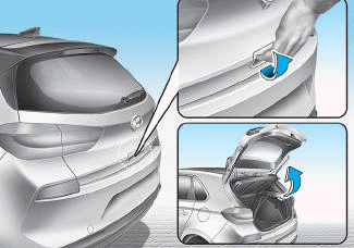
■ 5 Door, Wagon
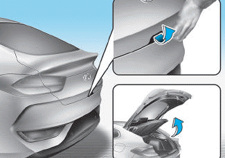
■ Fastback

Copyright © 2025 www.hi30.net