Hyundai i-30: Installing a Child Restraint System (CRS) / Securing a Child Restraint System with the “ISOFIX Anchorage System”
To install an i-Size or ISOFIX-compatible Child Restraint System in either of the rear outboard seating positions:
1. Move the seat belt buckle away from the ISOFIX anchorages.
2. Move any other objects away from the anchorages that could prevent a secure connection between the Child Restraint System and the ISOFIX anchorages.
3. Place the Child Restraint System on the vehicle seat, then attach the seat to the ISOFIX anchorages according to the instructions provided by the Child Restraint System manufacturer.
4. Follow the instructions of the Child Restraint System's manufacturer for proper installation and connection of the ISOFIX attachments on the Child Restraint System to the ISOFIX anchorages.
WARNING
Take the following precautions when using the ISOFIX system:
- Read and follow all installation instructions provided with your Child Restraint System.
- To prevent the child from reaching and taking hold of unretracted seat belts, buckle all unused rear seat belts and retract the seat belt webbing behind the child. Children can be strangled if a shoulder belt becomes wrapped around their neck and the seat belt tightens.
- NEVER attach more than one Child Restraint System to a single anchorage. This could cause the anchor or attachment to come loose or break.
- Always have the ISOFIX system inspected by your dealer after an accident. An accident can damage the ISOFIX system and may not properly secure the Child Restraint System.
 ISOFIX anchorage and top-tether
anchorage (ISOFIX anchorage
system) for children
ISOFIX anchorage and top-tether
anchorage (ISOFIX anchorage
system) for children
The ISOFIX system holds a Child
Restraint System during driving and in
an accident.This system is designed to
make installation of the Child Restraint
System easier and reduce the possibility
of improperly installing your
Child Restraint System...
 Securing a Child Restraint
System seat with “Top-tether
Anchorage” system
Securing a Child Restraint
System seat with “Top-tether
Anchorage” system
Top-tether anchorages for Child
Restraint Systems are located on the
rear of the seatbacks.
1. Route the Child Restraint System
top-tether strap over the seatback...
Other information:
Hyundai i30 (PD) 2018-2025 Service Manual: Electric WGT Control Actuator
Description and operation Desrcription Installed on the turbocharger, the Electric Waste Gate Actuator operates the valve in the Waste Gate Turbocharger (WGT) and regulates the amount of compressed air by using the ECM’s signals...
Hyundai i30 (PD) 2018-2025 Service Manual: Hood Assembly
Components and components location Component Location 1. Hood assembly Repair procedures Replacement • Be careful not to damage the hood and body...
Categories
- Manuals Home
- 3rd Generation i30 Owners Manual
- 3rd Generation i30 Service Manual
- Shift-lock system. Shift-lock release
- Theft-alarm system
- Auto door lock/unlock features
- New on site
- Most important about car
Air bag - supplemental restraint system
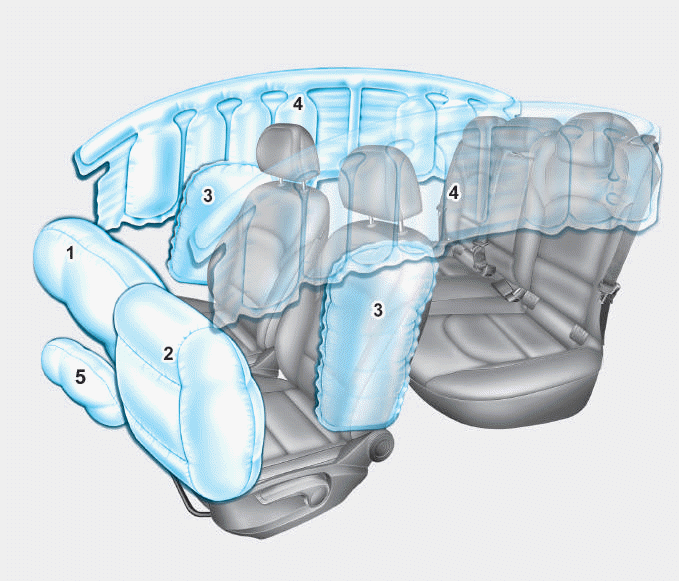
1. Driver’s front air bag
2. Passenger’s front air bag
3. Side air bag*
4. Curtain air bag*
5. Knee air bag*
6. Front passenger air bag ON/OFF
switch
