Hyundai i-30: SRSCM / Side Impact Sensor (SIS)
Components and components location
| Components |
| 1. Front Pressure
Side Impact Sensor (P-SIS) |
2. Front Gravity
Side Impact Sensor (G-SIS) |
Repair procedures
| Removal |
Front Pressure Side Impact Sensor
|

| 1. |
Disconnect the battery negative cable, and wait for at least three minutes
before beginning work.
|
| 2. |
Remove the front door trim.
(Refer to Body - "Front Door Trim")
|
| 3. |
Remove the front impact sensor (A) mounting bolt and disconnect the
front impact sensor connector (B).
|
Front Gravity Side Impact Sensor
| 1. |
Disconnect the battery negative cable and wait for at least three minutes
before beginning work.
|
| 2. |
Remove the door scuff trim.
(Refer to Body - "Interior Trim")
|
| 3. |
Remove the center pillar trim.
(Refer to Body - "Interior Trim")
|
| 4. |
Remove the front impact sensor (A) mounting bolt and disconnect the
front impact sensor connector (B).
|
| Installation |
Pressure Side Impact Sensor
| 1. |
Install the new pressure side impact sensor with the screw (A) then
connect the pressure side impact sensor connector.
|
| 2. |
Install the front door trim.
(Refer to Body - "Front Door Trim")
|
| 3. |
Reconnect the battery negative cable.
|
| 4. |
After installing the pressure side impact sensor, confirm proper system
operation:
|
Front Gravity Side Impact Sensor
|
| 1. |
Install the new side impact sensor with the bolt then connect the side
impact sensor connector.
|
| 2. |
Install the center pillar trim.
(Refer to Body - "Interior Trim")
|
| 3. |
Install the door scuff trim.
(Refer to Body - "Interior Trim")
|
| 4. |
Reconnect the battery negative cable.
|
| 5. |
After installing the Side Impact Sensor, confirm proper system operation
:
|
Rear Gravity Side Impact Sensor
|
| 1. |
Install the new side impact sensor with the bolt then connect the side
impact sensor connector.
|
| 2. |
Install the luggage side trim.
(Refer to Body - "Luggage Side Trim")
|
| 3. |
Reconnect the battery negative cable.
|
| 4. |
After installing the Side Impact Sensor, confirm proper system operation
:
|
 Front Impact Sensor (FIS)
Components and components location
Components
1. Front Impact
Sensor (FIS)
Description and operation
Description
•
The front impact sensors (FIS) are installed on the upper of the side
panel in Front End Module (FEM)...
 Passenger Airbag (PAB) ON/OFF Switch
Description and operation
Description
•
Driver can control the passenger airbag operating Condition (Enable
or Disable) by using this PAB ON/OFF switch...
Other information:
Hyundai i30 (PD) 2018-2025 Owner's Manual: Mounting bracket for roof carrier
To install or remove a roof carrier, you can use the mounting bracket and cover on the roof. When you install a roof carrier, use the following procedure. 1. Insert a slim tool(coin or flat blade driver) into the slot and slide the cover toward the arrow on the cover...
Hyundai i30 (PD) 2018-2025 Owner's Manual: Limitations of the System
The LKA system may operate prematurely even if the vehicle does not depart from the intended lane, OR, the LKA system may not warn you if the vehicle leaves the intended lane under the following circumstances: When the lane and road conditions are poor It is difficult to distinguish the lane marking from the road surface or the lane marking is faded or not clearly marked...
Categories
- Manuals Home
- 3rd Generation i30 Owners Manual
- 3rd Generation i30 Service Manual
- Brake/clutch fluid
- Exhaust System (DPF) Warning Light. Glow Indicator Light
- Drive mode integrated control system
- New on site
- Most important about car
Door locks
Operating door locks from outside the vehicle
Mechanical key
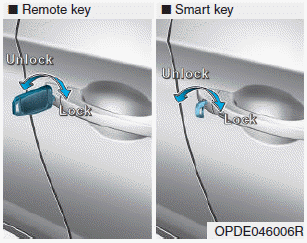
Turn the key toward the rear of the vehicle to unlock and toward the front of the vehicle to lock.
If you lock/unlock the driver's door with a key, a driver’s door will lock/unlock automatically.

Copyright © 2025 www.hi30.net