Hyundai i-30: Heating, Ventilation and Air Conditioning / Special service tools
Hyundai i30 (PD) 2018-2025 Service Manual / Heating, Ventilation and Air Conditioning / Special service tools
| Special Service Tools |
|
Tool (Number and name) |
Illustration |
Use |
|
09977-3R000 Disc & hub assembly bolt remover |
|
Removal and installation of disc & hub assembly. |
 Troubleshooting
Troubleshooting
Problem Symptoms Table
Before replacing or repairing air conditioning components, first determine if
the malfunction is due to the refrigerant charge, air flow or compressor...

Other information:
Hyundai i30 (PD) 2018-2025 Owner's Manual: Front seat head restraints
The driver’s and front passenger’s seats are equipped with adjustable head restraints for the passengers safety and comfort. Adjusting the height up and down To raise the head restraint: 1. Pull it up to the desired position (1). To lower the head restraint: 1...
Hyundai i30 (PD) 2018-2025 Service Manual: Components and components location
..
Categories
- Manuals Home
- 3rd Generation i30 Owners Manual
- 3rd Generation i30 Service Manual
- Trip computer
- Engine coolant
- To activate the ISG system
- New on site
- Most important about car
Turn signals and lane change signals
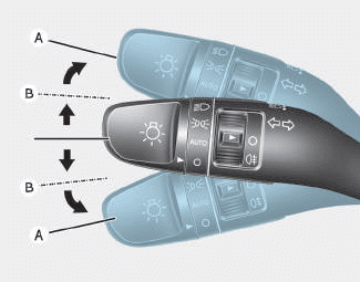
To signal a turn, push down on the lever for a left turn or up for a right turn in position (A). To signal a lane change, move the turn signal lever slightly and hold it in position (B).The lever will return to the OFF position when released or when the turn is completed.

Copyright © 2025 www.hi30.net