Hyundai i-30: Engine Mechanical System / Specifications
Hyundai i30 (PD) 2018-2025 Service Manual / Engine Mechanical System / Specifications
| Specifications |
|
Description |
Specification |
Limit |
||
|
General |
||||
|
Type |
In-line, DOHC |
|
||
|
Number of cylinders |
4 |
|
||
|
Bore |
71.6 mm (2.8189 in.) |
|
||
|
Stroke |
92.0 mm (3.6220 in.) |
|
||
|
Total displacement |
1.482 cc (90.43 cu.in) |
|
||
|
Compression ratio |
10.5 : 1 |
|
||
|
Firing order |
1 - 3 - 4 - 2 |
|
||
|
Valve timing |
||||
|
Intake valve |
Opens |
BTDC 111.7° - BTDC 41.7° |
|
|
|
Closes |
BBDC 38.7° - ABDC 31.3° |
|
||
|
Exhaust valve |
Opens |
BBDC 44.4° - ABDC 5.6° |
|
|
|
Closes |
ATDC 3° - ATDC 50.3° |
|
||
|
Cylinder head |
||||
|
Flatness of gasket surface |
Less than 0.05 mm (0.0025 in.) |
|
||
|
Less than 0.02 mm (0.0008 in.) / 100 x 100 |
||||
|
Flatness of manifold |
Intake |
Less than 0.1 mm (0.0039 in.) |
|
|
|
mounting surface |
Exhaust |
Less than 0.1 mm (0.0039 in.) |
|
|
|
Camshaft |
||||
|
Camheight |
Intake |
36.125 mm (1.4222 in.) |
|
|
|
Exhaust |
35.73 mm (1.4067 in.) |
|
||
|
Journal outer Diameter |
Intake |
No.1: 36.454 - 36.468 mm |
|
|
|
(1.43877 - 1.43574 in.) |
||||
|
No.2,3,4,5: 22.964 - 22.978 mm |
|
|||
|
(0.90409 - 0.90464 in.) |
||||
|
Exhaust |
No.1: 36.454 - 36.468 mm |
|
||
|
(1.43877 - 1.43574 in.) |
||||
|
No.2,3,4,5: 22.954 - 22.968 mm |
|
|||
|
(0.90370 - 0.90425 in.) |
||||
|
End play |
0.10 - 0.20 mm (0.0039 - 0.0078 in.) |
|
||
|
Valve |
||||
|
Valve length |
Intake |
100.94 mm (3.9740 in.) |
|
|
|
Exhaust |
101.14 mm (3.9818 in.) |
|
||
|
Stem outer diameter |
Intake |
5.460 - 5.475 mm (0.2149 - 0.2155 in.) |
|
|
|
Exhaust |
5.443 - 5.455 mm (0.2142 - 0.2247 in.) |
|
||
|
Face angle |
45.25° - 45.75° |
|
||
|
Thickness of valve head (margin) |
Intake |
0.85 - 1.15 mm (0.0334 - 0.0452 in.) |
|
|
|
Exhaust |
1.15 - 1.45 mm (0.0452 - 0.0570 in.) |
|
||
|
Valve stem to valve guide clearance |
Intake |
0.025 - 0.052 mm (0.00098 - 0.00204 in.) |
|
|
|
Exhaust |
0.055 - 0.069 mm (0.00216 - 0.00271 in.) |
|
||
|
Valve guide |
||||
|
Valve length |
Intake |
45.8 - 46.2 mm (1.8031 - 1.8188 in.) |
|
|
|
Exhaust |
45.8 - 46.2 mm (1.8031 - 1.8188 in.) |
|
||
|
Valve spring |
||||
|
Free length |
Intake |
Exhaust |
|
|
|
47.9 mm (1.8858 in.) |
54.3 mm (2.1377 in.) |
|
||
|
Load |
16.7 ± 0.8 kgf.m / 35.5 mm (36.81 ± 1.76 lb / 1.3976 in.) |
23.5 ± 1.1 kgf.m / 35.5 mm (51.81 ± 2.42 lb / 1.3976 in.) |
|
|
|
30.2 ± 1.4 kgf.m / 26.8 mm (65.57 ± 3.08 lb / 1.0905 in.) |
36.2 ± 1.2 kgf.m / 27.7 mm (79.81 ± 2.64 lb / 1.0905 in.) |
|
||
|
Out of squareness |
1.5° MAX |
|
||
|
Cylinder block |
||||
|
Cylinder bore |
71.60 - 71.63 mm (2.8188 -2.8200 in.) |
|
||
|
Flatness of gasket surface |
Less than 0.05 mm (0.0020 in) |
|
||
|
Less than 0.02 mm (0.0008 in) / 100 x 100 |
||||
|
Piston |
||||
|
Piston outer diameter |
71.555 - 71.585 mm (2.8171 - 2.8183 in) |
|
||
|
Piston to cylinder clearance |
0.035 - 0.055 mm (0.0014 - 0.0022 in) |
|
||
|
Ring groove width |
No. 1 ring groove |
1.235 - 1.250 mm (0.0486 - 0.0492 in.) |
|
|
|
No. 2 ring groove |
1.03 - 1.05 mm (0.0405 - 0.0413 in) |
|
||
|
Oil ring groove |
1.995 - 2.010 mm (0.0785 - 0.0791 in) |
|
||
|
Piston ring |
||||
|
Side clearance |
No. 1 ring |
0.05 - 0.08 mm (0.0020 - 0.0031 in) |
|
|
|
No. 2 ring |
0.04 - 0.08 mm (0.0015 - 0.0031 in) |
|
||
|
Oil ring |
0.040 - 0.085 mm (0.0016 - 0.0033 in) |
|
||
|
End gap |
No. 1 ring |
0.13 - 0.18 mm (0.0051 - 0.0071 in) |
|
|
|
No. 2 ring |
0.25 - 0.35 mm (0.0098 - 0.0137 in) |
|
||
|
Oil ring |
0.10 - 0.40 mm (0.0039 - 0.0157 in) |
|
||
|
Piston pin |
||||
|
Piston pin outer diameter |
17.997 - 18.000 mm (0.7085 - 0.7086 in) |
|
||
|
Piston pin hole inner diameter |
18.007 - 18.011 mm (0.7089 - 0.7090 in.) |
|
||
|
Piston pin hole clearance |
0.007 - 0.014 mm (0.00027 - 0.00055 in.) |
|
||
|
Connecting rod small end hole inner diameter |
18.005 - 18.011 mm (0.7088 - 0.7090 in) |
|
||
|
Connecting rod small end hole clearance |
0.005 - 0.014 mm (0.00019 - 0.00055 in) |
|
||
|
Connecting rod |
||||
|
Connecting rod big end inner diameter |
42.000 - 42.018 mm (1.6535-1.6542 in) |
|
||
|
Connecting rod bearing oil clearance |
0.018 - 0.036 mm (0.0007 - 0.0014 in) |
|
||
|
Side clearance |
0.10 - 0.25 mm (0.0039 - 0.0098 in) |
|
||
|
Crankshaft |
||||
|
Main journal outer diameter |
47.942 - 47.960 mm (1.8875 - 1.8882 in.) |
|
||
|
Pin journal outer diameter |
38.954 - 38.972 mm (1.5336 - 1.5343 in) |
|
||
|
Main bearing oil clearance |
No.1,2,4,5 : 0.012 - 0.030 mm (0.0005 - 0.0012 in) NO.3 : 0.018 - 0.036 mm (0.0007 - 0.0014 in.) |
|
||
|
End play |
0.10 - 0.28 mm (0.0039 - 0.0110 in) |
|
||
|
Engine oil |
||||
|
Oil quantity |
Total |
4.3(1.13 U.S.gal., 4.54 U.S.qt., 3.78 lmp.qt.) ~ 4.6 L (1.21 U.S.gal., 4.86 U.S.qt., 4.04 lmp.qt.) |
When replacing a short engine or a block assembly |
|
|
Oil pan |
3.8 L (1.00 U.S.gal., 4.01 U.S.qt., 3.34 lmp.qt.) |
|
||
|
Drain and refill |
4.2 L (1.10 U.S.gal., 4.43 U.S.qt., 3.69 lmp.qt.) |
Including oil filter |
||
|
Oil grade |
Specifications |
0W-20 / API SN+/SP or ILSAC GF-6 Information • Refer to the "Lubrication System" for recommended SAE viscosity number. |
|
|
|
Oil pressure (at 1000rpm) |
0.9 bar or above |
Oil temperature in oil pan : 110 ± 2°C (230±3.6°F) |
||
|
Cooling method |
||||
|
Cooling system |
Forced circulation with water pump |
|
||
|
Coolant quantity |
6.1 L (1.61 U.S.gal., 6.44 U.S.qt., 5.36 lmp.qt.) |
|
||
|
Reservoir tank cap |
Main valve opening temperature |
93.16 - 122.58 kpa |
|
|
|
(0.95 - 1.25 kg/cm2, 13.51 - 17.78 psi) |
||||
|
Vacuum valve opening temperature |
Max 6.8 kpa |
|
||
|
(Max 0.07 kg/cm2, 0.99 psi) |
||||
Tightening Torques
|
Item |
N.m |
kgf.m |
lb-ft |
|
Engine mounting |
|||
|
Engine mounting bracket and body fixing blot |
63.7 - 83.3 |
6.5 - 8.5 |
47.0 - 61.4 |
|
Engine mounting insulator to engine mounting support bracket fixing nut |
88.3 - 107.9 |
9.0 - 11.0 |
65.1 - 79.6 |
|
Engine mounting support bracket and engine support bracket fixing bolt |
58.8 - 73.5 |
6.0 - 7.5 |
43.4 - 54.2 |
|
Engine mounting support bracket and engine support bracket fixing nut |
58.8 - 73.5 |
6.0 - 7.5 |
43.4 - 54.2 |
|
Transaxle mounting bracket and body fixing bolt |
63.7 - 83.3 |
6.5 - 8.5 |
47.0 - 61.4 |
|
Transaxle mounting bracket and transaxle mounting support bracket fixing
bolt |
88.3 - 107.9 |
9.0 - 11.0 |
65.1 - 79.6 |
|
Roll rod bracket and sub frame fixing bolt |
49.0 - 63.7 |
5.0 - 6.5 |
36.2 - 47.0 |
|
Roll rod bracket to roll rod support bracket fixing bolt |
107.9 - 127.5 |
11.0 - 13.0 |
79.6 - 94.0 |
|
Main moving system |
|||
|
Connecting rod bearing cap bolt |
[10.7 - 14.7] + [88 - 92°] |
[1.1 - 1.5] + [88 - 92°] |
[7.9 - 10.8] + [88 - 92°] |
|
Crankshaft main bearing cap bolt |
[17.6 - 21.5] + [88 - 92°] |
[1.8 - 2.2] + [88 - 92°] |
[13.0 - 15.9] + [88 - 92°] |
|
Fly wheel bolt |
73.5 - 83.3 |
7.5 - 8.5 |
54.2 - 61.4 |
|
Timing chain |
|||
|
Timing chain cover bolt (A) |
28.4 - 31.8 |
2.9 - 3.2 |
20.9 - 23.1 |
|
Timing chain cover bolt (B) |
44.1 - 53.9 |
4.5 - 5.5 |
32.5 - 39.8 |
|
Timing chain cover bolt (C) |
44.1 - 53.9 |
4.5 - 5.5 |
32.5 - 39.8 |
|
Crankshaft damper pulley bolt |
[75.5 - 81.4 ] + [76° - 78°] |
[7.7 - 8.3] + [76° - 78°] |
[55.7 - 60.0] + [76° - 78°] |
|
Timing chain tensioner bolt |
9.8 - 11.8 |
1.0 - 1.2 |
7.2 - 8.7 |
|
Timing chain cam to cam guide bolt |
9.8 - 11.8 |
1.0 - 1.2 |
7.2 - 8.7 |
|
Timing chain tensioner arm bolt |
9.8 - 11.8 |
1.0 - 1.2 |
7.2 - 8.7 |
|
Timing chain guide bolt |
18.6 - 21.6 |
1.9 - 2.2 |
13.7 - 15.9 |
|
Idler bolt |
44.1 - 53.9 |
4.5 - 5.5 |
32.5 - 39.7 |
|
Drive belt tensioner bolt |
19.6 - 26.5 |
2.0 - 2.7 |
14.5 - 19.5 |
|
Cylinder head |
|||
|
High pressure fuel pipe nut |
26.5 - 32.4 |
2.7 - 3.3 |
19.5 - 23.9 |
|
High pressure fuel pump fixing bolt |
12.7 - 14.7 |
1.3 - 1.5 |
9.4 - 10.8 |
|
Cylinder head cover bolt |
[3.9 - 5.9] + [7.8 - 9.8] |
[0.4 - 0.6] + [0.8 - 1.0] |
[2.9 - 4.3] + [5.8 - 7.2] |
|
Intake OCV & center bolt |
[22.5 - 26.4] + [28° - 32°] |
[2.3 - 2.7] + [28° - 32°] |
[16.6 - 19.5] + [28° - 32°] |
|
Exhaust OCV & center bolt |
[22.5 - 26.4] + [32° - 36°] |
[2.3 - 2.7] + [32° - 36°] |
[16.6 - 19.5] + [32° - 36°] |
|
Camshaft bearing cap bolt (M6) |
11.7 - 13.7 |
1.2 - 1.4 |
8.6 - 10.1 |
|
Camshaft bearing cap bolt (M8) |
18.6 - 22.5 |
1.9 - 2.3 |
13.7 - 16.6 |
|
Cylinder head bolt |
[12.7 - 16.7] + [140 - 145°] + [140 - 145°] |
[1.3 - 1.7] + [140 - 145°] + [140 - 145°] |
[9.4 - 12.3] + [140 - 145°] + [140 - 145°] |
|
Cylinder block |
|||
|
Ladder frame bolt |
18.6 - 23.5 |
1.9 - 2.4 |
13.7 - 17.3 |
|
Oil jet bolt |
8.8 - 12.7 |
0.9 - 1.3 |
6.5 - 9.4 |
|
Cooling system |
|||
|
Water pump bolt |
9.8 - 11.8 |
1.0 - 1.2 |
7.2 - 8.7 |
|
Water pump housing bolt |
18.6 - 23.5 |
1.9 - 2.4 |
13.7 - 17.4 |
|
Heater pipe bolt & nut |
18.6 - 23.5 |
1.9 - 2.4 |
13.7 - 17.4 |
|
Water inlet fitting bolt & nut |
18.6 - 23.5 |
1.9 - 2.4 |
13.7 - 17.3 |
|
Integrated Thermal Management Module (ITM) |
18.6 - 23.5 |
1.9 - 2.4 |
13.7 - 17.3 |
|
Lubrication system |
|||
|
Oil filter |
11.8 - 15.7 |
1.2 - 1.6 |
8.7 - 11.6 |
|
Oil pump |
18.6 - 23.5 |
1.9 - 2.4 |
13.7 - 17.3 |
|
Oil pan bolt |
9.8 - 11.8 |
1.0 - 1.2 |
7.2 - 8.7 |
|
Oil pan drain plug |
34.3 - 44.1 |
3.5 - 4.5 |
25.2 - 32.4 |
|
Oil pressure Control Solenoid Valve |
9.8 - 11.8 |
1.0 - 1.2 |
7.2 - 8.7 |
|
Intake and exhaust system |
|||
|
Air intake hose clamp bolt |
3.9 - 5.9 |
0.4 - 0.6 |
2.9 - 4.3 |
|
Air cleaner assembly bolt |
7.8 - 9.8 |
0.8 - 1.0 |
5.8 - 7.2 |
|
Intake manifold bolt |
18.6 - 23.5 |
1.9 - 2.4 |
13.7 - 17.4 |
|
Vacuum hose & pipe mounting bolt |
9.8 - 11.8 |
1.0 - 1.2 |
7.2 - 8.7 |
|
Lower catalytic converter stay (WCC) |
39.2 - 44.1 |
4.0 - 4.5 |
28.9 - 32.5 |
|
Upper catalytic converter stay (WCC) |
18.6 - 23.5 |
1.9 - 2.4 |
13.7 - 17.4 |
|
Turbo charger oil drain pipe bolt (to cylinder block) |
9.8 - 11.8 |
1.0 - 1.2 |
7.2 - 8.7 |
|
Turbo charger oil feed pipe bracket bolt |
9.8 - 11.8 |
1.0 - 1.2 |
7.2 - 8.7 |
|
Turbo charger oil feed pipe (to cylinder block) |
9.8 - 11.8 |
1.0 - 1.2 |
7.2 - 8.7 |
|
Turbo charger oil drain pipe bolt (to turbo charger) |
22.5 - 26.4 |
2.3 - 2.7 |
16.6 - 19.5 |
|
Turbo charger oil feed pipe eye bolt (to turbo charger) |
22.5 - 26.4 |
2.3 - 2.7 |
16.6 - 19.5 |
|
Turbo charger water feed pipe (to cylinder block) |
9.8 - 11.8 |
1.0 - 1.2 |
7.2 - 8.7 |
|
Turbo charger water feed pipe eye bolt (to turbo charger) |
26.4 - 32.3 |
2.7 - 3.3 |
19.5 - 23.8 |
|
Turbo charger water drain pipe mounting bracket bolt(to head cover) |
9.8 - 11.8 |
1.0 - 1.2 |
7.2 - 8.7 |
|
Turbo charger water drain pipe mounting bracket bolt (to heat protector) |
9.8 - 11.8 |
1.0 - 1.2 |
7.2 - 8.7 |
|
Turbo charger water drain pipe eye bolt(to turbo charger) |
26.4 - 32.3 |
2.7 - 3.3 |
19.5 - 23.8 |
|
Turbo manifold module nut |
34.3 - 42.2 |
3.5 - 4.3 |
25.3 - 31.1 |
|
EGR cooler mounting bolt |
22.5 - 26.4 |
2.0 - 2.5 |
16.6 - 19.5 |
|
Intercooler inlet pipe mounting bolt |
18.6 - 23.5 |
1.9 - 2.4 |
13.7 - 17.4 |
|
Intercooler mounting bolt |
6.8 - 10.7 |
0.7 - 1.1 |
5.0 - 7.9 |
|
Catalytic convertor mounting nut (WCC) |
39.2 - 49.0 |
4.0 - 4.5 |
28.9 - 36.1 |
|
Muffler monting nut |
39.2 - 58.8 |
4.0 - 6.0 |
28.9 - 43.4 |

 Repair procedures
Compression Pressure Inspection
•
If there is lack of power, excessive oil consumption or poor
fuel economy, measure te compression pressure...
Other information:
Hyundai i30 (PD) 2018-2025 Owner's Manual: LKA system operation
To activate/deactivate the LKA system: With the ignition switch in the ON position, press the LKA system button located on the instrument panel on the right hand side of the steering wheel. The indicator in the cluster display will initially illuminate white...
Hyundai i30 (PD) 2018-2025 Service Manual: Components and components location
..
Categories
- Manuals Home
- 3rd Generation i30 Owners Manual
- 3rd Generation i30 Service Manual
- Engine coolant
- FCA sensor
- Front windscreen wiper service position
- New on site
- Most important about car
Power windows
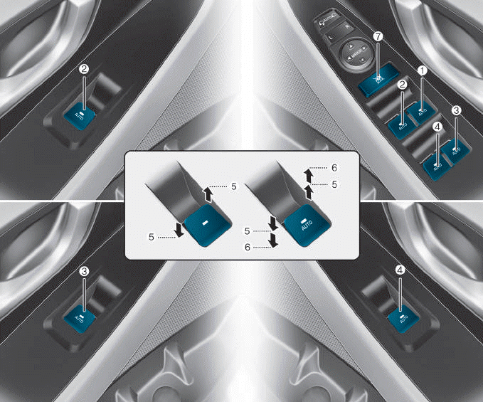
(1) Driver’s door power window
switch
(2) Front passenger’s door power
window switch
(3) Rear door (right) power window
switch
(4) Rear door (left) power window
switch
(5) Window opening and closing
(6) Automatic power window
(7) Power window lock switch

Copyright © 2025 www.hi30.net