Hyundai i-30: Tire Pressure Monitoring System / TPMS Receiver
Description and operation
| Description |
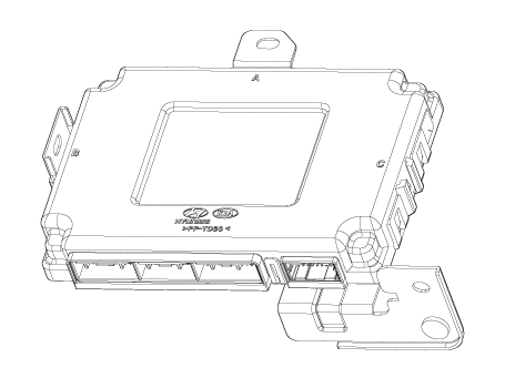
TPMS Receiver : BCM(body control module) integrated management
| 1. |
Mode
|
| 2. |
Overview
|
| Operation |
| 1. |
General Function
|
| 2. |
General Conditions to Learn New Sensors :
|
| 3. |
General Conditions to Un-Learn a sensor that is removed :
|
Repair procedures
| Removal |
| 1. |
Disconnect the negative (-) battery terminal.
|
| 2. |
Remove the glove box.
(Refer to Body - "Glove Box Upper Cover Assembly")
|
| 3. |
Remove the smart key unit.
(Refer to Body - "Smart Key Unit")
|
| 4. |
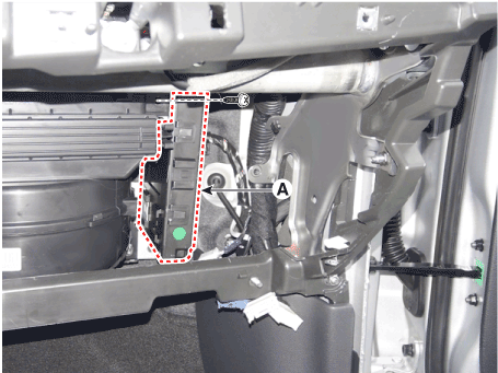
Remove the body control module (A).
|
| 5. |
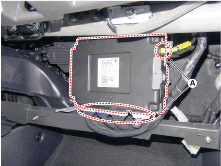
Disconnect the connectors (A) and then remove the body control mudule
(B).
|
| Installation |
| 1. |
Install the body control module.
|
| 2. |
Install the smart key unit.
|
| 3. |
Install the glove box upper cover assembly.
|
| Diagnosis procedure by using diagnostic device |
The main contents of diagnostic method using diagnostic device are as follows:
| 1. |
Connect self-diagnosis connector (16 pins) located in the lower driver
side crash pad to self-diagnosis device, and then turn on the self-diagnosis
device after key is ON.
|
| 2. |
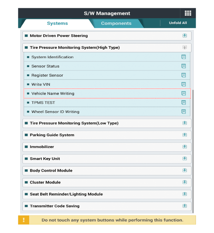
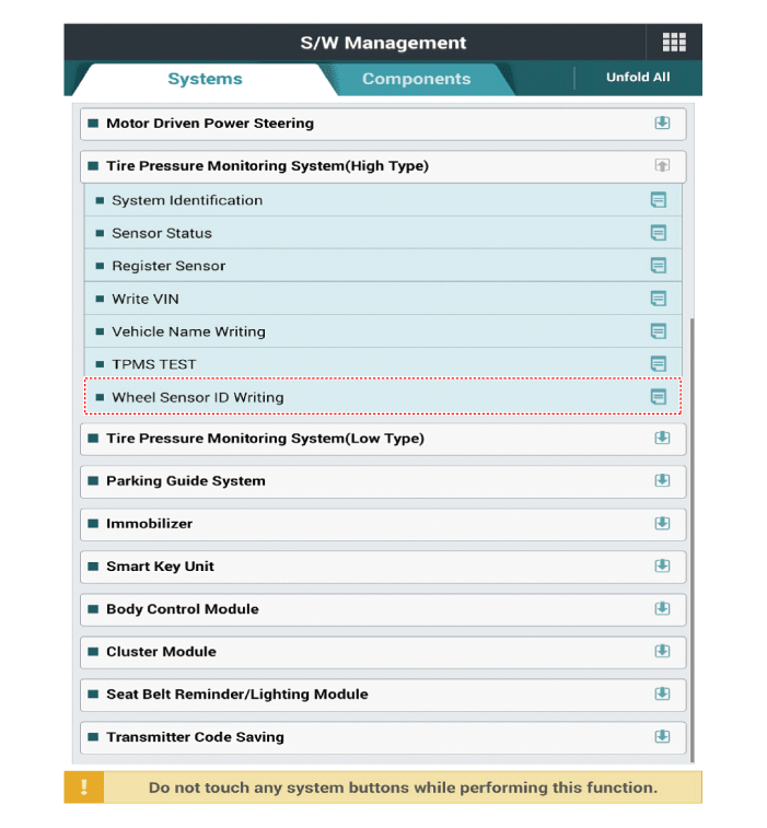
Select the "vehicle model" and "TPMS" on GDS vehicle selection screen,
then select OK.
|
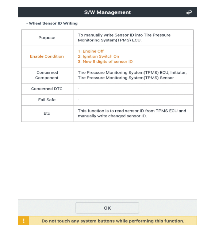
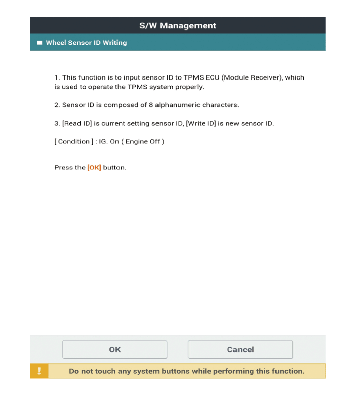
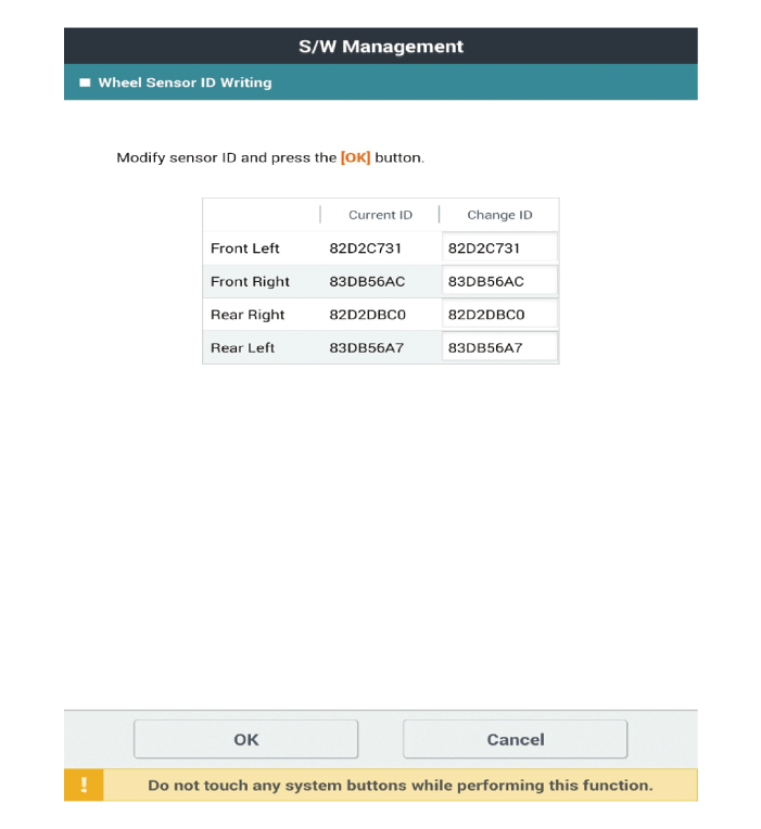
[Vehicle Name Writing Method]
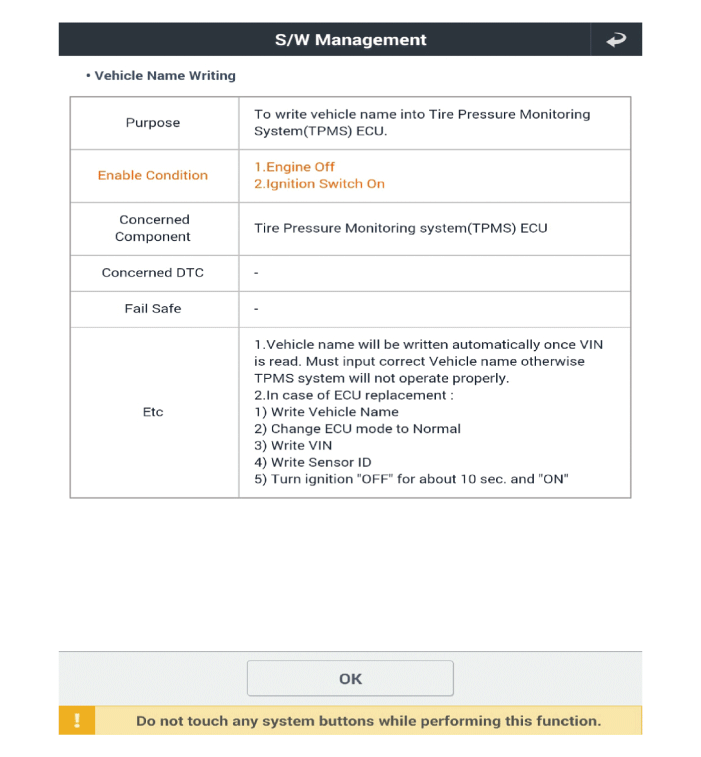
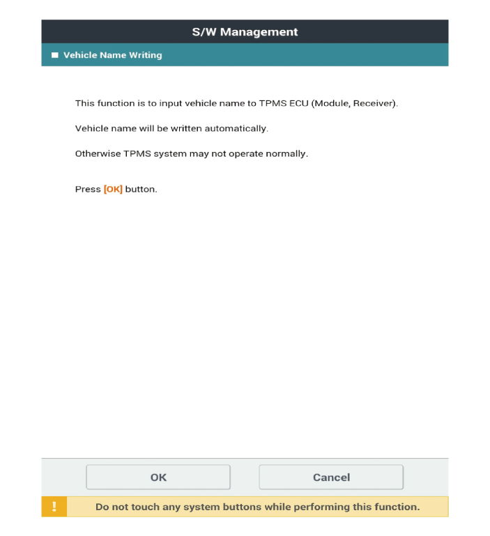
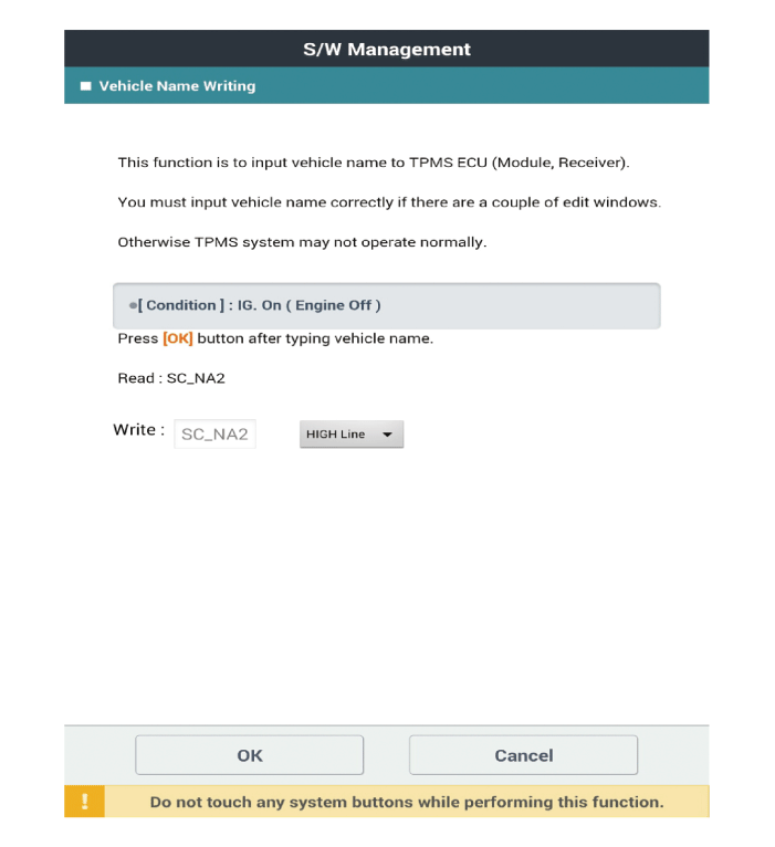
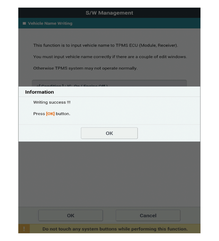
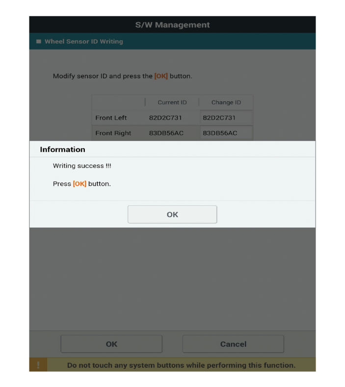
[Wheel Sensor ID Writing Method]
 TPMS Sensor
Description and operation
Description
1.
General description
WU is a sensor placed in the tire that reports pressure and temperature...
Other information:
Hyundai i30 (PD) 2018-2025 Owner's Manual: Securing a Child Restraint System with a lap/shoulder belt
When not using the ISOFIX system, all Child Restraint Systems must be secured to a rear seat with the lap part of a lap/shoulder belt. Installing a Child Restraint System with a lap/shoulder belt To install a Child Restraint System on the rear seats, do the following: 1...
Hyundai i30 (PD) 2018-2025 Service Manual: Engine and Transaxle Assembly
Repair procedures Removal • Use fender covers to avoid damaging painted surfaces. • To avoid damage, unplug the wiring connectors carefully while holding the connector portion...
Categories
- Manuals Home
- 3rd Generation i30 Owners Manual
- 3rd Generation i30 Service Manual
- Scheduled maintenance services
- Engine coolant
- Trip computer
- New on site
- Most important about car
Warning light and message
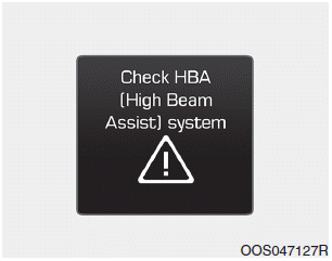
When the High Beam Assist (HBA)
System is not working properly, the
warning message will come on for a
few second. After the message disappears,
the master warning light ( )
will illuminate.
Copyright © 2025 www.hi30.net

