Hyundai i-30: Tire Pressure Monitoring System / TPMS Sensor
Description and operation
| Description |
| 1. |
General description
WU is a sensor placed in the tire that reports pressure and temperature.
The WU is mounted inside the wheels, fixed to the valve. The angle between
the valve and the housing of the WU is variable.
This allows adaptation to various types of rims.
The Wheel Unit is made of a PCB supporting the electronic hardware and
encapsulated inside a housing which is potted with polyurethane.
It is self-powered by a battery and includes all systems for parameter
measurement (pressure, temperature and centrifugal acceleration and
optionally rotation direction), RF transmission and LF detection.
To achieve the specified battery lifetime, the WU supports various measurement
and transmission timings, depending on WU operation mode.
For RF transmission, WU uses an internal antenna.
|
| 2. |
First Block Mode
: When vehicle start driving, Sensor enter Mode First Block.
Typical period of RF emissions is 16 sec. for 40 times for Auto-learning
and Auto-location function.
|
| 3. |
Driving Mode
: After 19 min. parking and then finishing Mode First Block mode, WU
enter Driving mode.
Typical period of RF emissions are 64 sec above 4g vehicle speed.
|
| 4. |
Parking Mode
: at below 3g Vehicle speed, enter Parking mode.
Typical periodicities of RF emissions are 13 hours.
|
Repair procedures
| Replacement |
| 1. |
Remove the wheel and tire.
|
| 2. |
Remove the valve core and deflate the tire.
|
| 3. |
Install the wheel tire to the tire change machine.
|
| 4. |
Push the tire as the illustration below.
|
| 5. |
Remove the TPMS sensor by loosening the nut.
|
| 6. |
Push the TPMS sensor into the valve hole on the rim.
|

| 7. |
Pre-assemble the nut on the TPMS sensor.
|
| 8. |
Tighten the TPMS sensor nut.
|
| 9. |
Remove the tire change machine.
|
| 10. |
Inject air into the tire until the beads are in the correct position.
|
| Inspection |
After installing TPMS sensor test methods Thai
| 1. |
Sealing washer on the outside rim of hole to be compressed.
|
| 2. |
The lower part of the valve housing, a fixed place (no metal brackets)
should be located.
|
| 3. |
Housing is at least one or more points on the surface of the rim should
contact.
|
| 4. |
The rim of the housing mounting height shall not exceed the height of
the chin.
[Faulty]
[Normally]
|
Diagnosis procedure by using diagnostic device
As manual for diagnosis methods by using diagnosis device, the main contents
are as follows:
| 1. |
Connect self-diagnosis connector (16pins) located in the lower of driver
side crash pad to self-diagnosis device, and then turn the self-diagnosis
device after key is ON.
|
| 2. |
Select the "vehicle model" and "TPMS" on GDS vehicle selection screen,
then select OK.
|
| Diagnostic Procedure Using a Diagnostic Instrument |
The following section describes how to diagnose faults using a diagnostic instrument.
| 1. |
Connect the diagnostic instrument to the self-diagnostic connector (16-pin)
beneath the crash pad on the side of driver's seat, and then turn on
the ignition to activate the diagnostic instrument.
|
| 2. |
In the GDS Vehicle Type Selection menu, select "Vehicle Type" and "TPMS"
System, and then opt for "OK."
|
[Register Sensor Method]
|
[Sensor Status Method]
|
 Description and operation
Description
TREAD Lamp
–
Tire Under Inflation / Leak Warning.
1.
Turn on condition
–
When tire pressure is below allowed threshold
–
When rapid leak is detected by the sensor...
 TPMS Receiver
Description and operation
Description
TPMS Receiver : BCM(body control module) integrated management
1.
Mode
(1)
Virgin State
–
The receiver as a sole part is shipped in this state...
Other information:
Hyundai i30 (PD) 2018-2025 Service Manual: Components and components location
..
Hyundai i30 (PD) 2018-2025 Owner's Manual: Auto door lock/unlock features
Impact sensing door unlock system (if equipped) All doors will be automatically unlocked when an impact causes the air bags to deploy. Speed sensing door lock system (if equipped) All doors will be automatically locked when vehicle speed exceeds 9 mph (15 km/h)...
Categories
- Manuals Home
- 3rd Generation i30 Owners Manual
- 3rd Generation i30 Service Manual
- Light bulbs
- Drive mode integrated control system
- Shift-lock system. Shift-lock release
- New on site
- Most important about car
Seat belt warning light
Seat belt warning
Driver’s seat belt warning
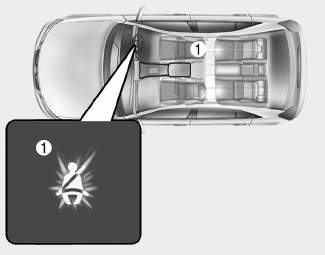
■ Instrument cluster
As a reminder to the driver, the seat belt warning light will illuminate for approximately 6 seconds each time you turn the ignition switch ON regardless of belt fastening.

Copyright © 2025 www.hi30.net