Hyundai i-30: AVN System / AVN(Audio Video Navigation) head unit
Hyundai i30 (PD) 2018-2025 Service Manual / Body Electrical System / AVN System / AVN(Audio Video Navigation) head unit
Components and components location
| Components |
[AVN Head Unit]
Connector Pin Information
|
No |
Connector A |
Connector B |
Connector C |
|
1 |
Rear door speaker (Left +) |
- |
B-CAN (High) |
|
2 |
Rear door speaker (Left -) |
Mic_Signal (+) |
C-CAN (High) |
|
3 |
- |
- |
- |
|
4 |
- |
- |
- |
|
5 |
- |
- |
- |
|
6 |
Camera power |
Illumination (+) |
- |
|
7 |
Camera video |
MM CAN (High) |
- |
|
8 |
- |
- |
B-CAN (Low) |
|
9 |
- |
- |
C-CAN (Low) |
|
10 |
- |
Battery (+) |
- |
|
11 |
DTC |
Battery (+) |
- |
|
12 |
Steering wheel remote |
Ground |
- |
|
13 |
Front door speaker (Left +) |
Ground |
- |
|
14 |
Front door speaker (Left -) |
- |
- |
|
15 |
Front door speaker (Right -) |
Mic_Signal (-) |
- |
|
16 |
Front door speaker (Right +) |
- |
- |
|
17 |
- |
- |
- |
|
18 |
- |
- |
- |
|
19 |
- |
Illumination (-) |
- |
|
20 |
Camera power ground |
MM CAN (Low) |
- |
|
21 |
Camera video ground |
- |
- |
|
22 |
- |
ACC |
|
|
23 |
- |
- |
|
|
24 |
- |
- |
|
|
25 |
- |
- |
|
|
26 |
Steering wheel remote grond |
- |
|
|
27 |
Rear door speaker (Right -) |
- |
|
|
28 |
Rear door speaker (Right +) |
- |
|
|
29 |
- |
- |
|
|
30 |
- |
- |
|
|
31 |
- |
- |
|
|
32 |
- |
IGN 1 |
|
|
33 |
Camera shield ground |
- |
|
|
34 |
- |
- |
|
|
35 |
- |
- |
|
|
36 |
- |
|
|
|
37 |
- |
||
|
38 |
Vehicle speed |
Repair procedures
| Removal |
|

| 1. |
Disconnect the negative (-) battery terminal.
|
| 2. |
2. Remove the center fascia panel.
(Refer to Cluster Pad - "Center Fascia Panel")
|
| 3. |
Remove the crash pad garnish assembly [RH].
(Refer to Crash Pad - "Crash pad side garnish assembly [RH]")
|
| 4. |
Remove the hazard switch.
(Refer to Lighting System - "Hazard Lamp Switch")
|
| 5. |
Remove the avn head unit assembly after loosening the mounting screws.
|
| 6. |
Remove the avn head unit assembly after disangaging the upper cover
(A).
|
| 7. |
Remove the avn head unit assembly (A) after loosening the mounting screws.
|
| 8. |
Remove the avn head unit after disconnecting the connectors and cable
(A).
|
| Installation |
| 1. |
Install the AVN head unit after connecting the AVN head unit connectors
and cable.
|
| 2. |
Install the center pascia panel.
|
| 3. |
Connect the negative (-) battery terminal.
|
|

 Description and operation
Description
AVN system
The AVN system has improved information search and easiness of manipulation
for the driver by simplifying the system operation experience and unifying the
display of the user information such as multimedia and car information...
 Speaker
Repair procedures
Inspection
Troubleshooting of the speakers
When handling the speakers :
•
Do not cause shock to the speakers by dropping or throwing them...
Other information:
Hyundai i30 (PD) 2018-2025 Owner's Manual: Suitability of each seating position for ISOFIX Child Restraint Systems according to ECE regulations - 5 Door,Wagon
IUF = Suitable for ISOFIX forward child restraints systems of universal category approved for use in the mass group. IL = Suitable for particular ISOFIX child restraints systems (CRS) given in the attached list. These ISOFIX CRS are those of the "specific vehicle", "restricted" or "semi-universal" categories...
Hyundai i30 (PD) 2018-2025 Service Manual: Description and operation
Description Rear Corner Radar is a system that measures the relative speed and distance from the following vehicles by using two electromagnetic wave radar sensors attached to the rear bumper, and detects any vehicle within the blind spot zone and gives off alarm...
Categories
- Manuals Home
- 3rd Generation i30 Owners Manual
- 3rd Generation i30 Service Manual
- Shift-lock system. Shift-lock release
- Auto door lock/unlock features
- Drive mode integrated control system
- New on site
- Most important about car
Gauges and meters
Speedometer
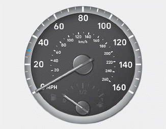
The speedometer indicates the speed of the vehicle and is calibrated in kilometers per hour (km/h) and/or miles per hour (MPH).
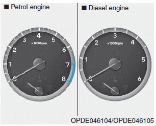
Tachometer

Copyright © 2025 www.hi30.net